5-24
SUPERSERVER 8047R-TRF+/7RFT+ USER'S MANUAL
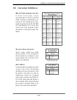
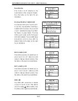
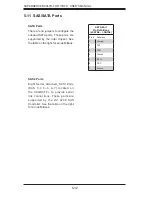
Power LED/Speaker
On JD1 header, pins 1-3 are for a
power LED and pins 4-7 are for the
speaker. Pins 4-7 are available for
connection to an external speaker. If
you wish to use the onboard speaker,
please close pins 6-7. See the table
on the right for speaker pin de
fi
nitions.
PWR LED Connector
Pin Defi nitions
Pin Setting De
fi
nition
Pin 1
Anode (+)
Pin2 Cathode
(-)
Pin3
NA
Speaker Connector
Pin Settings
Pin Setting De
fi
nition
Pins 4-7
External Speaker
Pins 6-7
Onboard Speaker
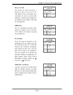
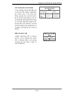
Serial Ports
COM1 is located on the rear I/O panel.
COM2, located close to PCI-E Slot2,
provides front access support. See the
table on the right for pin de
fi
nitions.
Serial Port Pin Defi nitions
Pin # De
fi
nition
Pin # De
fi
nition
1
DCD
6
DSR
2
RXD
7
RTS
3
TXD
8
CTS
4
DTR
9
RI
5
Ground
10
NC
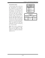
Overheat LED/Fan Fail
The JOH1 header is used to connect
an LED to provide warning of chassis
overheating. This LED will blink to
indicate a fan failure. Refer to the table
on right for pin de
fi
nitions.
OH/Fan Fail LED
States
State Message
Solid
Overheat
Blinking
Fan Fail
Overheat LED
Pin Defi nitions
Pin# De
fi
nition
1
5vDC
2
OH Active
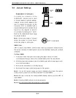
Chassis Intrusion
The Chassis Intrusion header is
designated JL1. Attach an appropriate
cable from the chassis to inform you of
a chassis intrusion when the chassis
is opened
Chassis Intrusion
Pin Defi nitions (JL1)
Pin# De
fi
nition
1
Intrusion Input
2
Ground
Содержание SUPERSERVER 8047R-7RFT+
Страница 5: ...Notes Preface v...
Страница 10: ...Notes x SUPERSERVER 8047R TRF 7RFT USER S MANUAL...
Страница 18: ...1 8 SUPERSERVER 8047R TRF 7RFT USER S MANUAL Notes...
Страница 142: ...A 2 SUPERSERVER 8047R TRF 7RFT USER S MANUAL Notes...

