background image

SUPERSERVER
1027R-WRF

®


S

UPER

USER'S MANUAL

Revision 1.0

Содержание SUPERSERVER 1027R-WRF

Страница 1: ...SUPERSERVER 1027R WRF SUPER USER S MANUAL Revision 1 0...

Страница 2: ...any such disputes Super Micro s total liability for all claims will not exceed the price paid for the hardware product FCC Statement This equipment has been tested and found to comply with the limits...

Страница 3: ...into a rack and check out the server configuration prior to powering up the system If your server was ordered without processor and memory components this chapter will refer you to the appropriate sec...

Страница 4: ...chapter when installing removing or reconfiguring SAS SATA or peripheral drives and when replacing system power supply units and cooling fans Chapter 7 BIOS The BIOS chapter includes an introduction t...

Страница 5: ...Notes Preface v...

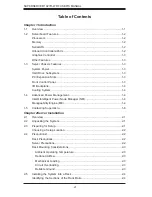
Страница 6: ...ement 1 4 Intel Intelligent Power Node Manager NM 1 4 Manageability Engine ME 1 4 1 5 Contacting Supermicro 1 6 Chapter 2Server Installation 2 1 Overview 2 1 2 2 Unpacking the System 2 1 2 3 Preparing...

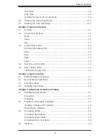
Страница 7: ...er LEDs 3 4 3 5 Power Supply LEDs 3 4 700W Power Supply LED 3 4 Chapter 4 System Safety 4 1 Electrical Safety Precautions 4 1 4 2 General Safety Precautions 4 2 4 3 ESD Precautions 4 3 4 4 Operating P...

Страница 8: ...ve Devices 6 1 Precautions 6 1 6 2 Control Panel 6 2 6 3 System Fans 6 2 System Fan Failure 6 3 6 4 Drive Bay Installation Removal 6 4 Accessing the Drive Bays 6 4 Hard Drive Installation 6 4 DVD Driv...

Страница 9: ...sink SNK P0047PS One 1 SC815 113 116 Intel DP X9 X8 PC air shroud MCP 310 19002 0N Five 5 40x56mm 4 pin PWM fans FAN 0086L4 One 1 70 cm front control cable 20 pin to 20 pin w tube CBL 0335L SAS SATA A...

Страница 10: ...g memory Note LRDIMM Reduced Load memory supports only 1333 1066 800 MHz speed memory Serial ATA An on chip Intel PCH C602 SATA controller is integrated into the X9DRW iF to provide a six port SATA su...

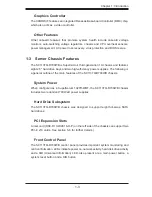
Страница 11: ...es The following is a general outline of the main features of the SC113TQ R700WB chassis System Power When configured as a SuperServer 1027R WRF the SC113TQ R700WB chassis includes two redundant 700 W...

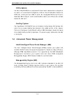
Страница 12: ...in IPMI that allows chassis fan speed to be determined by system temperature The power supply module also includes a cooling fan 1 4 Advanced Power Management Intel Intelligent Power Node Manager NM T...

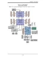
Страница 13: ...1 x16 x16 x16 J1 Right Slot PCIE 3 0x16 DMI PE3 PE2 PE1 QPI QPI CPU Front DMI PE1 PE2 PE3 P0PE3 J3 Left Slot PCIE 3 0x16 x16 x4 Lane4 7 UL1 I350AM2 JLAN1 RJ45 JLAN2 RJ45 LaneReversal PolarityInversion...

Страница 14: ...Address Super Micro Computer B V Het Sterrenbeeld 28 5215 ML s Hertogenbosch The Netherlands Tel 31 0 73 6400390 Fax 31 0 73 6416525 Email sales supermicro nl General Information support supermicro n...

Страница 15: ...any way If the server itself shows damage you should file a damage claim with the carrier who delivered it Decide on a suitable location for the rack unit that will hold the SuperServer 1027R WRF It...

Страница 16: ...llation stabilizers should be attached to the rack In multiple rack installations the racks should be coupled together Always make sure the rack is stable before extending a component from the rack Yo...

Страница 17: ...omised Mechanical Loading Equipment should be mounted into a rack so that a hazardous condition does not arise due to uneven mechanical loading Circuit Overloading Consideration should be given to the...

Страница 18: ...hich may mean the assembly procedure will differ slightly The following is a guideline for installing the SuperServer 1027R WRF into a rack with the rack rails provided You should also refer to the in...

Страница 19: ...server rack Attach the inner rail extension to stabilize the chassis within the rack Installing the Inner Rails Figure 2 2 1 Place the inner rack extensions on the side of the chassis aligning the hoo...

Страница 20: ...me direction 2 Adjust both the short and long brackets to the proper distance so that the rail fits snugly into the rack 3 Secure the long bracket to the front side of the outer rail with two M5 screw...

Страница 21: ...Chapter 2 Server Installation 2 7 Figure 2 4 Installing the Outer Rails to the Rack SCALE 0 380 1 2 1 3 1 3...

Страница 22: ...ter rails are installed on the rack 2 Line chassis rails with the front of the rack rails 3 Slide the chassis rails into the rack rails keeping the pressure even on both sides you may have to depress...

Страница 23: ...tend out the front of the rack Larger chassis should be positioned to balance the weight between front and back If a bezel is included on your server remove it Then attach the two front brackets to ea...

Страница 24: ...p the two handles on either side and pull the unit straight out until it locks you will hear a click 2 Remove the screws securing the top cover to the chssis 3 Slide the cover toward the rear of the c...

Страница 25: ...he hard drives have been properly installed and all connections have been made Checking the Drives 1 For servicing the hard drives you will need to remove the top chassis cover 2 If you need to remove...

Страница 26: ...2 12 SUPERSERVER 1027R WRF USER S MANUAL Notes...

Страница 27: ...tton to reboot the system Power This is the main power button which is used to apply or turn off the main system power Turning off system power with this button removes the main power but keeps standb...

Страница 28: ...irflow in the system or the ambient room temperature being too warm Check the routing of the cables and make sure all fans are present and operating normally You should also check to make sure that th...

Страница 29: ...LAN2 when flashing NIC1 Indicates network activity on LAN1 when flashing HDD Indicates IDE channel activity when flashing Power Indicates power is being supplied to the system s power supply units Thi...

Страница 30: ...ns on replacing failed drives 3 5 Power Supply LEDs This chassis provides several options which may include hot swappable cold swappable and redundant power supplies Some power supplies include an LED...

Страница 31: ...it has more than one power supply cord Disconnect two power supply cords before servicing to avoid electrical shock When working around exposed electrical circuits another person who is familiar with...

Страница 32: ...Follow these rules to ensure general safety Keep the area around the SuperServer 1027R WRF clean and free of clutter The SuperServer 1027R WRF weighs approximately 33 lbs 15 kg when fully loaded When...

Страница 33: ...ll components and printed circuit boards PCBs in their antistatic bags until ready for use Touch a grounded metal object before removing the board from the antistatic bag Do not let components or PCBs...

Страница 34: ...s practice is not strictly followed Figure 4 1 Installing the Onboard Battery LITHIUM BATTERY BATTERY HOLDER Please handle used batteries carefully Do not damage the battery in any way a damaged batte...

Страница 35: ...hat the size and weight of the serverboard can cause it to bend if handled improperly which may result in damage To prevent the serverboard from bending keep one hand under the center of the board to...

Страница 36: ...power cord last and always remove it before adding removing or changing any hardware components Make sure that you install the processor into the CPU socket before you install the CPU heatsink Cautio...

Страница 37: ...RNING Press down on Load the Lever labeled Close 1st Pull lever away from the socket 3 With the lever labeled Close 1st fully retracted gently push down on the Open 1st lever to open the load plate Li...

Страница 38: ...PU on the socket Do not move the CPU horizontally or vertically Do not rub the CPU against the surface or against any pins of the socket to avoid damaging the CPU or the socket Caution You can only in...

Страница 39: ...te with the CPU inside the socket Lock the lever labeled Close 1st first then lock the lever labeled Open 1st second Use your thumb to gently push the load levers down to the lever locks OPEN1st OPEN1...

Страница 40: ...nk on top of the CPU so that the four mounting holes are aligned with those on the Motherboard s and the Heatsink Bracket underneath 3 Screw in two diagonal screws i e the 1 and the 2 screws until jus...

Страница 41: ...o prevent damage done to the CPU or the CPU socket 1 Unscrew the heatsink screws from the motherboard in the sequence as shown in the illustration below 2 Gently wriggle the heatsink to loosen it from...

Страница 42: ...ATA 0 5 Note these cables are not provided or connected with the SuperServer 1027R WRF Connecting Power Cables The X9DRW iF has a pre conneted 24 pin primary power supply connector designated JPW1 for...

Страница 43: ...ous I O ports Figure 5 2 Rear Panel I O Ports Rear I O Ports 1 COM Port 1 Turquoise 6 Back Panel USB Port 3 2 Back Panel USB Port 0 7 Gigabit LAN 1 3 Back Panel USB Port 1 8 Gigabit LAN 2 4 IPMI_Dedic...

Страница 44: ...emory slots starting with DIMM 1A For best memory performance please install memory modules of the same type and same speed on the memory slots as indicated on the tables below 2 Insert each DIMM modu...

Страница 45: ...MF1 P1 DIMMC1 P1 DIMMD1 2 CPUs 8 DIMMs CPU1 CPU2 P1 DIMMA1 P1 DIMMB1 P2 DIMME1 P2 DIMMF1 P1 DIMMC1 P1 DIMMD1 P2 DIMMG1 P2 DIMMH1 2 CPUs 9 12 DIMMs CPU1 CPU2 P1 DIMMA1 P1 DIMMB1 P2 DIMME1 P2 DIMMF1 P1...

Страница 46: ...vices the amount of memory that remains available for operational use will be reduced when 4 GB of RAM is used The reduction in memory availability is disproportional See the following table for detai...

Страница 47: ...rd into the riser card pushing down with your thumbs evenly on both sides of the card 4 Slide the add on card into the riser card and attach the add on card bracket in place of the PCI slot shield 5 S...

Страница 48: ...2C1 LED3 LED1 COM2 JTAG OF CPLD SXB1A SXB1B CPU PCI E 3 0 x16 x16 P1 DIMMC1 CPU1 P1 DIMMC2 P1 DIMMD2 P1 DIMMD1 UID SXB2 CPU2 PCI E3 0 X16 LAN2 CPU2 LAN1 P1 DIMMB2 P1 DIMMA1 P1 DIMMA2 P1 DIMMB1 USB2 3...

Страница 49: ...Chapter 3 JI2C1 JI2C2 SMB to PCI E Slots Open Normal JPB1 BMC Enable Pins 1 2 Enabled JPG1 VGA Enable Pins 1 2 Enabled JPL1 LAN1 LAN2 Enable Pins 1 2 Enabled JWD1 Watch Dog Pins 1 2 Reset LED Descrip...

Страница 50: ...tandby Power Connector LAN1 2 G bit Ethernet Ports 1 2 IPMI LAN IPMI_Dedicated LAN SATA SCU 0 3 4 7 Serial_Link SATA SCU Connections 0 3 4 7 for X9DRW 3F SCU 0 3 for X9DRW iF SP1 Onboard Buzzer Intern...

Страница 51: ...5 COM 18 COM 6 5V 19 COM 7 COM 20 Res NC 8 PWR_OK 21 5V 9 5VSB 22 5V 10 12V 23 5V 11 12V 24 COM 12 3 3V 12V 8 pin PWR Connector Pin Definitions JPW2 3 Pins Definition 1 through 4 Ground 5 through 8 1...

Страница 52: ...Pin Definitions JF1 Pin Definition 1 PW_ON 2 Ground Overheat Fan Fail LED OH Connect an LED cable to pins 7 and 8 of Front Control Panel to use the Overheat Fan Fail Power Fail and UID LED connections...

Страница 53: ...nector is located on pins 15 and 16 of JF1 This connection is used to provide LED indication of power being supplied to the system See the table on the right for pin definitions Power LED Pin Definiti...

Страница 54: ...hernet ports LAN1 2 are located on the I O backplane on the motherboard to provide internet connections In addition an IPMI_ Dedicated LAN located above USB 0 1 ports on the backplane provides KVM sup...

Страница 55: ...ent via Hardware Monitoring in IPMI See Chapter 5 for more details See the table on the right for pin definitions Power LED Speaker On JD1 header pins 1 3 are used for power LED indication and pins 4...

Страница 56: ...on the motherboard For more information on IPMI please refer to the IPMI User s Guide posted on our Website http www supermicro com UID Switch Pin Definition 1 Ground 2 Ground 3 Button In 4 Ground UID...

Страница 57: ...monitors power supply fan and system temperatures See the table on the right for pin definitions PWR SMB Pin Definitions JI2C1 Pin Definition 1 Clock 2 Data 3 PWR Fail 4 Ground 5 3 3V Port 80 Header...

Страница 58: ...or pin definitions DOM Power Connector A power connector for SATA DOM Disk_On_Module devices is located at JSD1 Connect an appropriate cable here to provide power support for your DOM devices DOM Powe...

Страница 59: ...ort their Wake On LAN function Instead the legacy WOL header was preserved JSTBY to provide convenience for some embedded customers who need an internal power source from the board See the table on th...

Страница 60: ...is used to clear CMOS which will also clear any passwords Instead of pins this jumper consists of contact pads to prevent accidentally clearing the contents of CMOS To Clear CMOS 1 First power down t...

Страница 61: ...d VGA Enable Disable Jumper JPG1 allows the user to enable the onboard VGA connector The default setting is 1 2 to enable the connection See the table on the right for jumper settings BMC Enable Jumpe...

Страница 62: ...LED Settings Color Definition Off No Connection or 10 Mbps Green 100 Mbps Amber 1 Gbps LAN Activity Indicator Right LED Settings Color Status Definition Off No Connections Yellow Flashing Active Acti...

Страница 63: ...UID Switch on Page 2 17 for more information UID LED Status Color State Status Blue On Unit Identified Blue On Unit Identified Note For more information on SATA HostRAID configuration please refer to...

Страница 64: ...is display does not appear click on the My Computer icon and then on the icon representing your CD ROM drive Finally double click on the S Setup icon Click the icons showing a hand writing on paper to...

Страница 65: ...l system information such as CPU temperature system voltages and fan status See the Figure below for a display of the SuperDoctor III interface Note The default User Name and Password for SuperDoctor...

Страница 66: ...er s Manual can be downloaded from the Supermicro web site at http www supermicro com products accessories software SuperDoctorIII cfm For Linux we recommend that you use the SuperoDoctor II applicati...

Страница 67: ...vent damage to any printed circuit boards PCBs it is important to handle them very carefully The following measures are generally sufficient to protect your equipment from ESD damage Precautions Use a...

Страница 68: ...rverboard Setup 6 3 System Fans Five 4 cm counter rotating fans provide the cooling for the system Each fan unit is actually made up of two fans joined back to back which rotate in opposite directions...

Страница 69: ...fans Two additional open slots are available so that up to two more fans may be added Replacing a System Fan Figure 6 2 1 Open the chassis while the system is running to determine which fan has faile...

Страница 70: ...M Drive For installing removing a DVD ROM drive you will need to gain access to the inside of the system by removing the top cover of the chassis Proceed to the DVD ROM Drive Installation section late...

Страница 71: ...w 4 Insert the drive carrier into its bay keeping the carrier oriented so that the hard drive is on the top of the carrier and the release button is on the right side When the carrier reaches the rear...

Страница 72: ...the backplane or obstruct the holes which aid in proper airflow Caution Regardless of how many hard drives are installed all drive carriers must remain in the drive bays to maintain proper airflow Cau...

Страница 73: ...ate from the drive bay The bezel can be removed by pulling out the hard drive beneath the DVD ROM then pulling the mini bezel forward If you are replacing a drive Locate the locking tab at the rear le...

Страница 74: ...o until the failed module has been replaced Replacement modules can be ordered directly from Supermicro see contact information in the Preface Removing Replacing the Power Supply Figure 6 6 1 Check th...

Страница 75: ...age When an option is selected in the left frame it is highlighted in white Often a text message will accompany it Note that BIOS has default text messages built in We retain the option to include omi...

Страница 76: ...Boot Features Quiet Boot This feature allows the user to select bootup screen display between POST messages and the OEM logo Select Disabled to display the POST messages Select Enabled to display the...

Страница 77: ...The options are Enabled and Disabled Power Button Function If this feature is set to Instant Off the system will power off immediately as soon as the user presses the power button If this feature is s...

Страница 78: ...lled in Socket 1 Socket 2 64 bit This item indicates if the CPU installed in Socket 1 or Socket 2 supports 64 bit technology Clock Spread Spectrum Select Enable to enable Clock Spectrum support which...

Страница 79: ...the hardware prefetcher will prefetch streams of data and instructions from the main memory to the L2 cache to improve CPU performance The options are Disabled and Enabled Adjacent Cache Line Prefetch...

Страница 80: ...heat dissipation The options are Disabled GV3 Disabled and Enabled GV3 Enabled Note GV3 is Intel Speedstep support used on older platforms Please refer to Intel s website for detailed information Turb...

Страница 81: ...anufacturer during which long duration power is maintained Long Duration Power Limit This item displays the user defined power limit in watts during which long duration power is maintained Factory Lon...

Страница 82: ...y significantly reduces CPU overhead by leveraging CPU architectural improvements freeing the system resource for other tasks The options are Disabled and Enabled DCA Support Select Enabled to use Int...

Страница 83: ...ink connections The options are Fast and Slow QPI Link Frequency Select Use this feature to select the desired QPI frequency The options are Auto 6 4 GT s 7 2 GT s and 8 0 GT s DIMM Configuration This...

Страница 84: ...es two areas of memory to run the same set of operations in parallel The options are Independent Mirroring and Lockstep DRAM RAPL Mode RAPL Running Average Power Limit provides mechanisms to enforce p...

Страница 85: ...rs found on a memory module When the CPU or I O issues a demand read command and the read data from memory turns out to be a correctable error the error is corrected and sent to the requestor the orig...

Страница 86: ...Controller Interface Controller 1 or Controller 2 The options are Disabled and Enabled Legacy USB Support Available when USB Functions is not Disabled Select Enabled to support legacy USB devices Sel...

Страница 87: ...SATA Controller 1 The options for Controller 0 are Disabled Enhanced and Compatible The Options for Controller 1 are Disabled and Enhanced AHCI Mode The following items are displayed when the AHCI Mod...

Страница 88: ...ure to select the Option ROM to boot the system when there are multiple Option ROMs available in the system The options are EFI Compatible ROM and Legacy ROM PCI Latency Timer Use this feature to set...

Страница 89: ...ail CPU1 SXB 1A OPROM CPU1 SXB 1B OPROM CPU1 SXB 1C OPROM CPU2 SXB2 PCI E 3 0 x16 OPROM Select Enabled to enable Option ROM support to boot the computer using a network interface from the slots specif...

Страница 90: ...Q 3 4 5 6 7 9 10 11 12 IO 2F8h IRQ 3 4 5 6 7 9 10 11 12 IO 3E8h IRQ 3 4 5 6 7 9 10 11 12 and IO 2E8h IRQ 3 4 5 6 7 9 10 11 12 Serial Port 2 Configuration Serial Port Select Enabled to enable a serial...

Страница 91: ...ap Unicode characters into one or more bytes The options are ANSI VT100 VT100 and VT UTF8 Bits Per second Use this feature to set the transmission speed for a serial port used in Console Redirection M...

Страница 92: ...played on a terminal and send it as text messages to a remote server The options are Disabled and Enabled Resolution 100x31 Select Enabled for extended terminal resolution support The options are Disa...

Страница 93: ...higher frequency than a Real time Clock RTC does in synchronizing multimedia streams providing smooth playback reducing the dependency on other timestamp calculation devices such as an x86 RDTSC Instr...

Страница 94: ...rt the Intel Trusted Execution Technology CPU TXT Trusted Execution Technology Feature Chipset TXT Trusted Execution Technology Feature Intel TXT LT SX Configuration This feature displays the followin...

Страница 95: ...or which is a unique name used in the world Add an Attempt Delete Attempts Commit Changes and Exit Save the changes and exit from the page Discard Changes and Exit Discard the changes and exit from th...

Страница 96: ...rom 0 second to 15 seconds The default setting is 0 second Port Configuration Information This menu displays the following information for a NIC port specified UEFI Driver Adapter PBA Chip Type PCI De...

Страница 97: ...vent logs that exceed the limit when the SMBIOS event log is full Select Do Nothing for the system to do nothing when the SMBIOS event log is full The options are Do Nothing and Erase Immediately SMBI...

Страница 98: ...t logging at bootup The options are Enabled and Disabled Erasing Settings Erase SEL Select Yes On next reset to erase all system event logs upon next system reboot Select Yes On every reset to erase a...

Страница 99: ...manually in the field If DHCP is selected the BIOS will search for a DHCP Dynamic Host Configuration Protocol server in the network that is attached to and request the next available IP address for t...

Страница 100: ...boot the system from the network connection Select UEFI to boot the system from the UEFI Built in EFI Shell The options are LAN Device UEFI Built in EFI Shell and Disabled USB Device BBS Priorities Ha...

Страница 101: ...puter Select Discard Changes and Exit and press Enter When the dialog box appears asking you if you want to exit the BIOS setup without saving click Yes to quit BIOS without saving the changes or clic...

Страница 102: ...er Defaults Select this feature and press Enter to save the current settings as the user s defaults When the dialog box appears asking you if you want to save values as user s defaults click Yes to sa...

Страница 103: ...with your system manufacturer for possible repairs These fatal errors are usually communicated through a series of audible beeps The numbers on the fatal error list on the following page correspond t...

Страница 104: ...A 2 SUPERSERVER 1027R WRF USER S MANUAL Notes...
Страница 105: ...support up to 512 GB of DDR3 1600 1333 1066 800 MHz speed registered ECC RDIMM LRDIMM SDRAM in two channel memory bus Memory sizes of 512 MB 1 GB 2 GB 4 GB 8 GB 16 GB or 32 GB size 1 35V 1 5V voltages...

Страница 106: ...WRF has five 5 4 cm system cooling fans System Input Requirements AC Input Voltage 100 240 VAC Rated Input Current 8 3A 100V to 3 8A 240V Rated Input Frequency 60 50 Hz Platinum 90 Platinum Level Powe...

Страница 107: ...1000 4 4 EN 61000 4 5 EN 61000 4 6 EN 61000 4 8 EN 61000 4 11 Safety CSA EN IEC UL 60950 1 Compliant UL or CSA Listed USA and Canada CE Marking Europe California Best Management Practices Regulations...

Страница 108: ...rform be reasonably expected to result in significant injury or loss of life or catastrophic property damage Accordingly Supermicro disclaims any and all liability and should buyer use or sell such pr...

Отзывы: