SC512 Chassis Manual
5-16
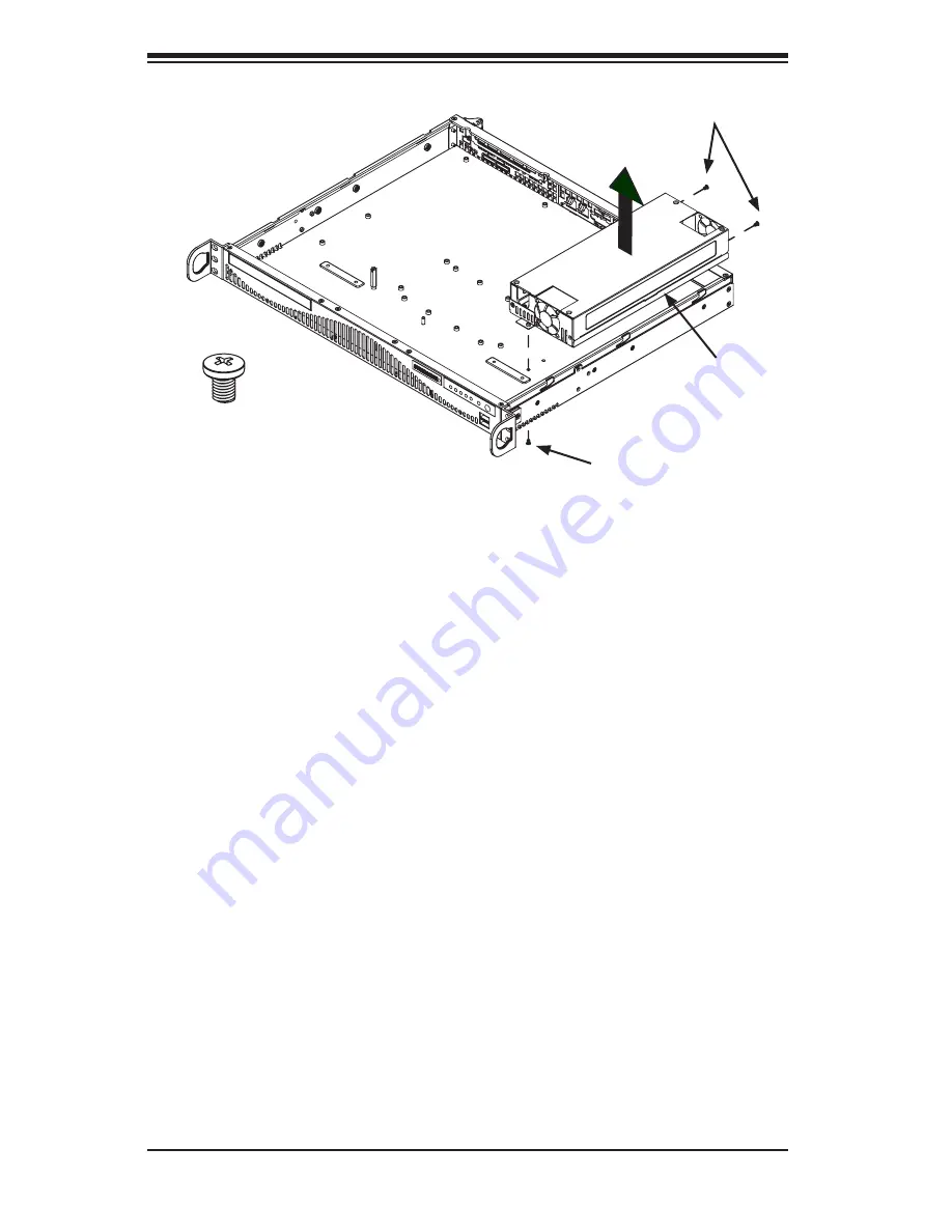
Remove this screw
Pan Head
6-32 x 5mm
[0.197]
Power Supply
Remove these screws
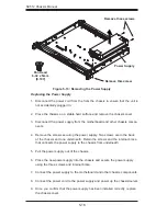
Replacing the Power Supply
Disconnect the power cord from the from the chassis to ensure that the unit is
1.
not accidentally plugged in.
Place the chassis on a stable hard surface and remove the chassis cover.
2.
Disconnect the power supply from the motherboard and other chassis compo-
3.
nents.
Remove the screws securing the power supply. Two screws are in the back
4.
of the chassis and one underneath. Retain the screws and the internal brace
that connects the power supply to the chassis from underneath.
Pull the power supply out of the chassis.
5.
Place the new power supply into the chassis and secure the power supply
6.
using the three screws and internal brace.
Connect the power supply to the motherboard and other chassis components.
7.
Connect the power cord to the power supply and power up the chassis/server.
8.
Once you confirm that the power supply has been installed correctly, replace
9.
the chassis cover.
Figure 5-13: Removing the Power Supply
Flat head
M4 x 4 mm
[0.157]
RAIL
Round head
M4 x 4 mm
[0.157]
Flat head
M5 x 12 mm [0.472]
Washer for M5
DVD-ROM CD-ROM FLOPPY DRIVE
Flat head
6-32 x 5 mm
[0.197]
Pan head
6-32 x 5 mm
[0.197]
Round head
3 x 5 mm
[0.197]
Pan head
6-32 x 5 mm
[0.197]
M/B
Flat head
6-32 x 5 mm
[0.197]
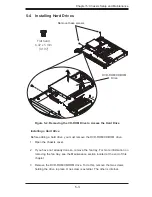
HARD DRIVE
Thumb screw
6-32 x 5 mm [0.197]
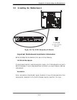
M/B standoff
6-32 to 6-32
M/B STANDOFF
M/B (CPU) standoff
M5 to 6-32
Round head
2.6 x 5 mm
[0.197]
Содержание SC512-260B
Страница 8: ...SC512 Chassis Manual viii Notes ...
Страница 26: ...SC512 Chassis Manual 3 10 Notes ...
Страница 30: ...SC512 Chassis Manual 4 4 Notes ...
Страница 48: ...SC512 Chassis Manual 5 18 Notes ...
Страница 69: ...B 3 Appendix B SC512F Power Supply Specifications Notes ...

