background image

S

UPER P4DC6/P4DC6+/P4DC6+II/P4DCE/P4DCE+/P4DCE+II User’s Manual

4-14

CPU Warning Temperatures

This item allows the user to set the CPU temperature threshold.  When the CPU

temperature reaches the threshold temperature set by the user, an alarm will

be activated and a warning message will be displayed onscreen.   The settings

are "Disabled", "50

0

C/122

0

F", "53

0

C/127

0

F", "56

0

C/133

0

F", "60

0

C/140

0

F", "63

0

C/

145

0

F", "66

0

C/151

0

F" and "70

0

C/158

0

F."

4-4.4

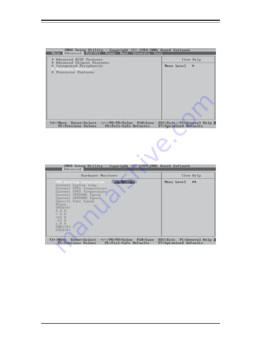
Hardware Monitors

When the item "Hardware Monitors" is highlighted, press the <Enter> key to

activate the Hardware Monitors sub-menu" (shown below).

Содержание P4DCE Plus II

Страница 1: ...SUPER P4DC6 SUPER P4DC6 SUPER P4DC6 II SUPER P4DCE SUPER P4DCE SUPER P4DCE II USER S MANUAL Revision 1 2c SUPER...

Страница 2: ...ABILITY TO USE THIS PRODUCT OR DOCUMENTATION EVEN IF ADVISED OF THE POSSIBILITY OF SUCH DAMAGES IN PARTICULAR THE VENDOR SHALL NOT HAVE LIABILITY FOR ANY HARDWARE SOFTWARE OR DATA STORED OR USED WITH...

Страница 3: ...st of what should be included in your mainboard box describes the features specifications and performance of the SUPER P4DC6 P4DC6 P4DC6 II P4DCE P4DCE P4DCE II mainboard and provides information abou...

Страница 4: ...erence 1 9 Motherboard Features 1 10 Intel 860 Chipset System Block Diagram 1 12 1 2 Chipset Overview 1 13 1 3 Special Features 1 14 1 4 PC Health Monitoring 1 14 1 5 ACPI PC 98 Features 1 16 1 6 Powe...

Страница 5: ...ng 2 14 2 7 Jumper Settings 2 14 Explanation of Jumpers 2 14 Rambus Speed 2 15 CMOS Clear 2 15 Keyboard Wake Up 2 16 USB Wake Up 2 16 SCSI Enable Disable 2 17 SCSI Termination Enable Disable 2 17 LAN...

Страница 6: ...for Service 3 6 Chapter 4 BIOS 4 1 Introduction 4 1 4 2 Running Setup 4 2 4 3 Main BIOS Setup 4 2 4 4 Advanced BIOS Setup 4 6 4 5 PCI PnPSetup 4 16 4 6 Power Management 4 17 4 7 Boot up Devices 4 21 4...

Страница 7: ...sing contact your retailer One 1 Supermicro mainboard and User s Manual One 1 ATA66 100 ribbon cable for IDE devices One 1 floppy ribbon cable One 1 Supermicro CD or diskettes containing drivers and u...

Страница 8: ...com Europe Address SuperMicro Computer B V Het Sterrenbeeld 28 5215 ML s Hertogenbosch The Netherlands Tel 31 0 73 6400390 Fax 31 0 73 6416525 Email sales supermicro nl General Information support sup...

Страница 9: ...Chapter 1 Introduction 1 3 Notes...

Страница 10: ...1 4 SUPER P4DC6 P4DC6 P4DC6 II P4DCE P4DCE P4DCE II User s Manual Figure 1 1 SUPER P4DC6 Image Note The P4DCE shares the same layout as the P4DC6 but with no onboard SCSI...

Страница 11: ...s The P4DCE shares the same layout as the P4DC6 but with no onboard SCSI The P4DC6 II shares the same layout as the P4DC6 but includes a heatsink over the VRM modules The P4DCE II shares the same layo...

Страница 12: ...CHB BANK 0 RAMBUS CHA BANK 1 RAMBUS CHB BANK 1 RAMBUS CHA BANK 0 PCI 4 PCI 3 PCI 64 1 AGP PRO PCI 64 2 PCI 1 PCI 2 CD 1 CD 2 IDE 1 IDE 2 J7 J6 P64H ICH2 AIC 7899 CH FAN3 ULTRA SCSI CH B ULTRA III LVD...

Страница 13: ...M1 COM2 COM1 COM2 Serial Port Connector CPU1 CPU2 CPU 1 and CPU 2 Sockets CPU CH OH FAN CPU Chassis Overheat Fan Headers J6 J7 IDE 1 IDE 2 Connector J15 Parallel Printer Port J16 PS 2 Keyboard Mouse C...

Страница 14: ...III LVD SE SCSI CH B ULTRA III LVD SE SCSI CH A JA2 JA3 JA1 BIOS BATTERY J20 JP4 J29 JWOR JPA1JPA2 CH FAN1 CH FAN2 JBT1 OH FAN JOH JP35 J32 WOL JP34 JP38 JP37 JP36 JP39 JP5 12 12 12 12 12 12 12 12 12...

Страница 15: ...2 Audio CD Inputs COM1 COM2 COM1 COM2 Serial Port Connector CPU1 CPU2 CPU 1 and CPU 2 Sockets CPU CH OH FAN CPU Chassis Overheat Fan Headers J6 J7 IDE 1 IDE 2 Connector J15 Parallel Printer Port J16 P...

Страница 16: ...H2 82801BA I O CH 82802AB Firmware Hub Expansion Slots One 4xAGP Pro 1 5v only Two 64 bit PCI 66 MHz 3 3v Four 32 bit PCI 33 MHz BIOS 4 Mb Firmware Hub Award Flash BIOS ACPI APM Power Management PAC 9...

Страница 17: ...Extended Capabilities Port PS 2 mouse and PS 2 keyboard ports 1 each 1 Raptor RAID controller P4DC6 and P4DC6 II only 1 LAN Ethernet port 1 infrared port 2 USB ports 2 USB headers 2 SCSI channels 1 a...

Страница 18: ...general block diagram and may not exactly represent all the features on your motherboard See the previous section for the actual specifications of each motherboard MCH CNR USB 0 1 2 3 ICH2 LPC I O FWH...

Страница 19: ...nd AGP The MCH supports up to 2 GB of RDRAM The RAMBUS dual channel memory bus can support full duplex memory bandwidth transfers at up to 3 2 GB s Different memory module speeds such as 600 MHz and 8...

Страница 20: ...included into which eliminates the need to use up a PCI slot to have RAID capability The Raptor RAID controller and adaptor utilizes a 64 bit bus provides 0 1 0 1 5 and 0 5 RAID levels and supports S...

Страница 21: ...sleep mode When in sleep mode the CPU will not run at full power thereby generating less heat CPU Overheat LED and Control This feature is available when the user enables the CPU overheat warning fun...

Страница 22: ...s such as CD ROMs network cards hard disk drives and printers This also includes consumer devices connected to the PC such as VCRs TVs telephones and stereos In addition to enabling operating system d...

Страница 23: ...s a system suspend button With this feature enabled the system will enter a SoftOff state when the user depresses the power button The monitor will be suspended and the hard drive will spin down Depre...

Страница 24: ...24 is necessary to support Intel Xeon CPUs Failure to provide such extra power will result in the CPUs becoming unstable after only a few minutes of operation See Section 2 6 for details on connectin...

Страница 25: ...e Super I O supports four 360K 720K 1 2M or 1 44M disk drives and data transfer rates of 250 Kbps 500 Kbps or 1 Mbps It also provides two high speed 16550 compatible serial communication ports UARTs o...

Страница 26: ...1 20 SUPER P4DC6 P4DC6 P4DC6 II P4DCE P4DCE P4DCE II User s Manual Notes...

Страница 27: ...gold contacts When handling chips or modules avoid touching their pins Put the motherboard and peripherals back into their antistatic bags when not in use For grounding purposes make sure your compute...

Страница 28: ...ng package Note VRM modules must also be installed P4DC6 and P4DCE only they are not included with the motherboard Retention brackets 2 Clips 2 Screws 4 These screws are to be used for mounting the mo...

Страница 29: ...ket 1 CPU socket 2 is automatically disabled if only one CPU is used Pin 1 7 Press the lever down until you hear it click into the locked position Socket lever in locked position 4 Secure the other re...

Страница 30: ...lthough a chassis may have both types metal fasteners are the most highly recommended because they ground the motherboard to the chas sis For this reason it is best to use as many metal fasteners as p...

Страница 31: ...mory 2 Insert each RDRAM module vertically into its slot Pay attention to the two notches along the bottom of the module to prevent inserting the module incorrectly 3 Gently press down on the RDRAM mo...

Страница 32: ...h their receptive points on the slot RIMM Slot Side View of RIMM Installation into Slot RIMM Tab Notch Tab Notch Tab Tab To Install With the tabs pulled outward insert the RIMM module vertically and p...

Страница 33: ...Bus Fan Failure LED Power Failure LED Network Interface Card LED I2C LED Chassis Intrusion Keyboard Lock Overheat and Speaker headers which are all located on JF1 Refer to the following section for d...

Страница 34: ...234567890123456789012345 Using an SSI 24 pin connector Using an ATX 20 pin connector Pin 1 Pin 1 Pin 12 Pin 24 Pin 13 Pin 10 Pin 11 Pin 20 Pins 1 thru 4 5 thru 8 Definition Ground 12v Table 2 1d 8 Pin...

Страница 35: ...also configure this button to function as a suspend button see the Power Button Mode setting in BIOS To turn the power off when set to suspend mode hold down the power button for at least four second...

Страница 36: ...ed the proper power cable not included to use this connection See Table 2 9 for pin definitions Pin Number 8 10 Definition 5v Signal Table 2 9 Pow er Fail LED Pin Definitions JF1 NIC LED The Network I...

Страница 37: ...ck The keyboard lock connection is lo cated on pins 22 and 24 of JF1 See Table 2 13 for pin definitions Pin Number 22 24 Function Ground Table 2 13 Keyboard Lock Pin Definitions JF1 Definition Keylock...

Страница 38: ...n JF1 connected you cannot use USB2 Table 2 17 Universal Serial Bus Pin Definitions Pin Definition 1 5v 2 P0 3 P0 4 Ground Pin Definition 1 5v 2 P0 3 P0 4 Ground J18 J19 Serial Ports Two serial connec...

Страница 39: ...sis Fan 1 2 3 4 and OH Fan respec tively Refer to Table 2 21 for pin definitions Table 2 21 Fan Header CPU Fan 1 2 Chassis Fan 1 4 OH Fan Pin Definitions Pin Number 1 2 3 Definition Ground black 12V...

Страница 40: ...solder pad on the printed circuit board See the motherboard layout pages for jumper locations Connector Pins Jumper Cap Setting Pin 1 2 short 3 2 1 3 2 1 Wake On Ring The Wake On Ring header is desig...

Страница 41: ...S Position 1 2 Position 2 3 Normal CMOS Clear T able 2 25 CMO S Clear Jum per Settings JBT 1 Jumper Position 1 2 2 3 Definition Normal CMOS Clear PCI 64 Speed Select P4DC6 P4DCE P4DC6 II P4DCE II only...

Страница 42: ...umper Position 1 2 2 3 Definition Disabled Enabled Table 2 27 Keyboard W ake Up Jum per Settings JPW AKE USB Wake Up Jumper JP39 is used in conjunction with the Keyboard Wake Up func tion in BIOS when...

Страница 43: ...per JPA1 controls SCSI channel A and JPA2 controls SCSI channel B The normal default setting is open to enable teminate both SCSI channels If you wish to connect external SCSI devices you should disab...

Страница 44: ...default setting with JP38 to prevent false alarms See Table 2 32 for jumper settings Jumper Position Open Closed Definition Disabled Enabled T able 2 32 Pow er Supply Alarm Enable Disable Jum per Set...

Страница 45: ...sk drive cable that came with your system has two connectors to support two drives This special cable should be used to take advantage of the speed this advanced technology offers The blue connector c...

Страница 46: ...tor Enable 12 Drive Select B 14 Drive Select A 16 Motor Enable 18 DIR 20 STEP 22 W rite Data 24 W rite Gate 26 Track 00 28 W rite Protect 30 Read Data 32 Side 1 Select 34 Diskette T able 2 35 Floppy C...

Страница 47: ...he edge of the motherboard if there are more pins not seated If the I O shield of your card is flush with the edge of the mother board the card should be inserted correctly 50 pin Legacy SCSI Connecto...

Страница 48: ...13 GND 14 GND 15 GND 16 GND 17 Termpwrd 18 Termpwrd 19 GND 20 GND 21 GND 22 GND 23 GND 24 GND 25 GND 26 GND 27 GND 28 GND 29 GND 30 GND 31 GND 32 GND 33 GND 34 GND Pin Number Function 35 DB 12 36 DB...

Страница 49: ...splay Screen Click the icons showing a hand writing on paper to view the readme files for each item Click the tabs to the right of these in order from top to bottom to install each item one at a time...

Страница 50: ...2 24 SUPER P4DC6 P4DC6 P4DC6 II P4DCE P4DCE P4DCE II User s Manual Notes...

Страница 51: ...or the keyboard and mouse 3 Remove all add on cards 4 Install a CPU making sure it is fully seated and connect the chassis speaker and the power LED to the motherboard Check all jumper settings as wel...

Страница 52: ...all types and versions of BIOS can be flashed depend ing on the modifications to the boot block code NOTE If you are a system integrator VAR or OEM a POST diagnostics card is recommended For I O port...

Страница 53: ...ase refer to Chapter 2 for additional information Note Check the Supermicro web site for recommended memory modules http www supermicro com TECHSUPPORT FAQs Memory_vendors htm Question How do I update...

Страница 54: ...er The supplied compact disc has quite a few drivers and programs that will greatly enhance your system We recommend that you review the CD and install the applications you need Applications on the CD...

Страница 55: ...that came with your disk drive for details on actual jumper locations and settings Question Why am I getting the message Pre Boot Agent Failed on the top left of my screen during system boot up Answer...

Страница 56: ...hen returning to the manufacturer the RMA number should be prominently displayed on the outside of the shipping carton and mailed prepaid or hand carried Shipping and handling charges will be ap plied...

Страница 57: ...and PS 2 compatible computers The AwardBIOS Flash chip stores the system parameters such type of disk drives video displays etc in its CMOS memory CMOS Complementary Metal Oxide Semiconductor a batter...

Страница 58: ...the screen during the POST Power On Self Test press the Del key to activate the Main Setup Menu Press DEL to enter SETUP 4 3 Main BIOS Setup All Main Setup options are described in this section The M...

Страница 59: ...These options allow the user to set the type of floppy disk drive installed in the system The settings are None 360K 5 25in 1 2M 5 25in 720K 3 5in 1 44M 3 5in and 2 88M 3 5in Swap Floppy Drive These o...

Страница 60: ...Primary Master Device The settings are None Auto and Manual Access Mode This item determines the location through which the AwardBIOS access the IDE Primary Master Device The settings are CHS LBA Lar...

Страница 61: ...ird party IDE bus master driver If your IDE hard drive and your system software both support Ultra DMA 33 select Auto to enable BIOS support The settings are Auto and Disabled Video This option allows...

Страница 62: ...memory available in the system The default setting for this option is 1024K 4 4 Advanced BIOS Setup Choose Advanced BIOS Setup from the AwardBIOS Setup Utility main menu with the Left Right arrow keys...

Страница 63: ...chipset or the keyboard controller should have control over Gate A20 The settings are Normal or Fast If set to Normal a pin in the keyboard controller controls Gate A20 If Fast is selected the chipse...

Страница 64: ...s useful when two computers are hooked up to a single monitor When enabled the user can toggle the display from one system to the other using the Tab key The function keys are diabled when the Console...

Страница 65: ...PCI slots and the CPU Normally the default settings for the Advanced Chipset Features listed in this section are pre configured by the manufacturer for optimal system performance It is not recommende...

Страница 66: ...the time in minutes between the thermal limit being exceeded and the system automatically shutting down The settings are 4 min 8 min 16 min and 32 min On Chip Primary PCI IDE If Enabled this option a...

Страница 67: ...m This option allows you to enable or disable the onboard AC97 modem The settings are Auto and Disabled Delay Prior to Thermal This section determines the time in minutes between the thermal limit bei...

Страница 68: ...8 IRQ4 2F8 IRQ3 3E8 IRQ4 2E8 IRQ3 and Auto Onboard Serial Port 2 This option allows the user to set the address and the corresponding IRQ for Serial Port 2 The settings are Disabled 3F8 IRQ4 2F8 IRQ3...

Страница 69: ...s This item sets the mode for Use IR Pins The settings are RxD2 TxD2 and IR Rx2Tx2 Onboard Parallel Port This option allows the user to set the address and the corresponding IRQ for the onboard Parall...

Страница 70: ...s the threshold temperature set by the user an alarm will be activated and a warning message will be displayed onscreen The settings are Disabled 500 C 1220 F 530 C 1270 F 560 C 1330 F 600 C 1400 F 63...

Страница 71: ...er key to activate the sub menu which is shown below CPU L1 L2 Cache Set this option to Enabled to activate the function of the CPU L1 and L2 caches The settings are Disabled and Enabled CPU L3 Cache...

Страница 72: ...ng Set this option to Enabled to activate the hyper threading function of the CPUs Enabling the hyper threading function makes each CPU appear as two to any programs that support it you must have OS s...

Страница 73: ...cts in system configuration and has resulted in system boot up failure then select Enabled to reset Extended System Configuration Data ESCD for the OS to reboot the system The settings are Enabled and...

Страница 74: ...m especially for HDD Power Down Doze Mode and Suspend Mode The settings are User Define Min Saving and Max Saving Video Off Method This item determines the manner in which the monitor is turned off Th...

Страница 75: ...a PCI card signal The settings are Enabled and Disabled Power On by Ring This item allows the AwardBIOS to enable system wake up from a ring signal The settings are Enabled and Disabled Wake Up on LAN...

Страница 76: ...ctivate the power on function through the keyboard Press the Enter key to enter the password Hot Key Power On This option allows the user to select the hot key to activate the power on function The se...

Страница 77: ...sequence Boot ROM Order This option determines the boot ROM order The settings are Adaptec 7899 and Any PCI Slot First Boot Device This item allows the user to select the device as the first boot up...

Страница 78: ...om another device rather than the ones that have been specified as the first second and third boot up devices The settings are Enabled and Disabled Virus Warning This item allows the user to choose th...

Страница 79: ...r s Password is highlighted on the Security Main Menu press the Enter key to activate the password screen When prompted type a password in the dialogue box to establish or to change the User s Passwor...

Страница 80: ...the letter Y and press Enter with the Exit without Saving field highlighted any of the changes you ve made in CMOS will not be saved when you exit the CMOS Setup Your system should then continue with...

Страница 81: ...l Defaults When the item Load Optimal Defaults is highlighted press the Enter key to activate the dialogue box Then press the Y key to load the default values that will provide the optimal system perf...

Страница 82: ...SUPER P4DC6 P4DC6 P4DC6 II P4DCE P4DCE P4DCE II User s Manual 4 26 Notes...

Страница 83: ...4 27 Chapter 4 AwardBIOS...

Страница 84: ...ngle long beep that sounds repeatedly Error Messages One or more of the following messages may be displayed if the BIOS detects an error during the POST This list includes messages for both the ISA an...

Страница 85: ...he adapter is installed correctly and all cables are correctly and firmly attached Also be sure the correct hard drive type is selected in Setup ERRORINITIALIZINGHARDDISKCONTROLLER Cannot initialize t...

Страница 86: ...ARITY ERROR messages when the segment that has caused the problem cannot be isolated OFFENDINGSEGMENT This message is used in conjunction with the I O CHANNEL CHECK and RAM PARITY ERROR messages when...

Страница 87: ...locked out Unlock the key BIOS detect the keyboard is locked P17 of the keyboard controller is pulled low Keyboard error or no keyboard present Cannot initialize the keyboard Make sure that the keyboa...

Страница 88: ...042 interface 2 Initialize 8042 self test 08h 1 Test special keyboard controller for Winbond 977 series Super I O chips 2 Enable keyboard interface 09h Reserved 0Ah l Disable PS 2 mouse interface opti...

Страница 89: ...1Dh Initial EARLY_PM_INIT switch 1Eh Reserved 1Fh Load keyboard matrix notebook platform 20h Reserved 21h HPM initialization notebook platform 22h Reserved 23h 1 Check validity of RTC value e g a valu...

Страница 90: ...Reserved 47h Initialize EISA slot 48h Reserved 49h 1 Calculate total memory by testing the last double word of each 64K page 2 Program writes allocation for AMD K5 CPU 4Ah Reserved 4Bh Reserved 4Ch R...

Страница 91: ...am chipset registers according to items described in Setup Auto configuration table 6Ch Reserved 6Dh 1 Assign resources to all ISA PnP devices 2 Auto assign ports to onboard COM ports if the correspon...

Страница 92: ...sign IRQs to PCI devices 7 Initialize APM 8 Clear noise of IRQs 86h Reserved 87h Reserved 88h Reserved 89h Reserved 90h Reserved 91h Reserved 92h Reserved 93h Read HDD boot sector information for Tren...

Страница 93: ...B 6 SUPER P4DC6 P4DC6 P4DC6 II P4DCE P4DCE P4DCE II User s Manual Notes...

Страница 94: ...p Code ErrorMessageDescription 1 short beep System boot 2 short beeps Incorrect CMOS setting 1 long 1 short DRAM error 1 long 2 short VGAerror 1 long 3 short Keyboard error 1 long 9 short ROM error Lo...

Страница 95: ...C 2 SUPER P4DC6 P4DC6 P4DC6 II P4DCE P4DCE P4DCE II User s Manual Notes...

Отзывы: