


6-2
S
UPER
S
ERVER 1027R-WTRFTP User's Manual
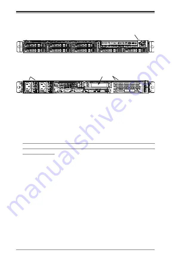
Figure 6-1. Chassis: Front and Rear Views
6-2 Control Panel
The control panel (located on the front of the chassis) must be connected to the JF1
connector on the serverboard to provide you with system status indications. These
wires have been bundled together as a ribbon cable to simplify the connection.
Connect the cable from JF1 on the serverboard to the appropriate header on the
Control Panel PCB (printed circuit board). Make sure the red wire plugs into pin 1
on both connectors.
Pull all excess cabling out of the airflow path.
The control panel LEDs inform you of system status. See "Chapter 3: System In-
terface" for details on the LEDs and the control panel buttons. Details on JF1 can
be found in "Chapter 5: Advanced Serverboard Setup."
6-3 System Fans
The 1027R-WTRFTP contains six counter-rotating fans. Each fan unit is actually
made up of two fans joined back-to-back, which rotate in opposite directions. This
counter-rotating action generates exceptional airflow and works to dampen vibra
-
tion levels.
Control Panel
Hard Drive Bays (8)
PCI Expansion Slots (w/riser card)
Rear I/O Ports (see Fig. 5.3)
Power Supplies
Содержание SuperServer 1027R-WTRFTP
Страница 1: ...SUPERSERVER 1027R WTRFTP USER S MANUAL 1 0...
Страница 5: ...v Preface Notes...
Страница 14: ...1 6 SUPERSERVER 1027R WTRFTP User s Manual Notes...
Страница 26: ...3 4 SUPERSERVER 1027R WTRFTP User s Manual Notes...
Страница 46: ...4 20 SUPERSERVER 1027R WTRFTP User s Manual Notes...
Страница 88: ...6 10 SUPERSERVER 1027R WTRFTP User s Manual Figure 6 5 Removing Replacing the Power Supply...
Страница 124: ...A 2 SUPERSERVER 1027R WTRFTP User s Manual Notes...
Страница 127: ...B 3 Appendix B System Specifications Notes...


