57
Chapter 3: Maintenance and Component Installation
DIMM Installation
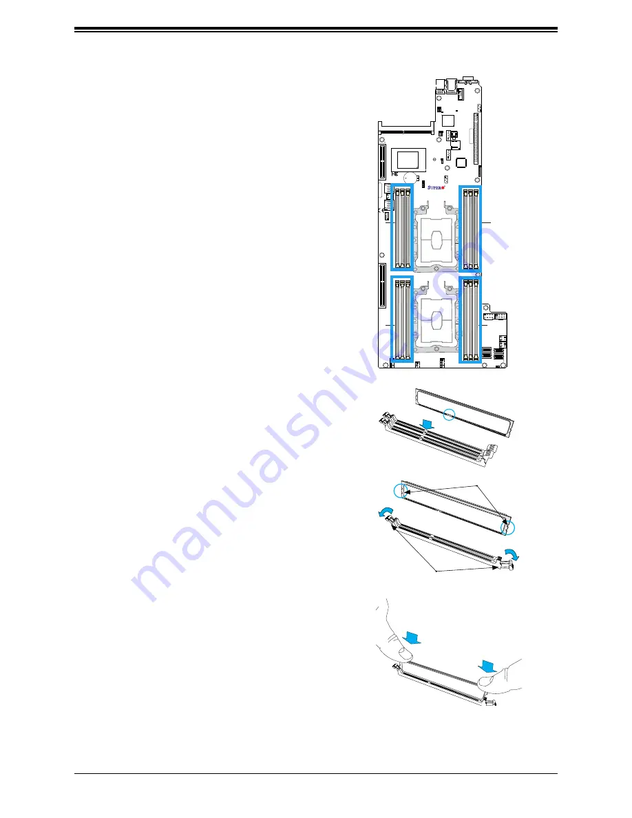
1. Insert DIMM modules in the following order: For
CPU1, begin with P1-DIMMC1, P1-DIMMB1,
P1-DIMMA1 then P1-DIMMF1, P1-DIMME1,
P1-DIMMD1. For CPU2, begin with P2-DIMMC1,
P2-DIMMB1, P2-DIMMA1 then P2-DIMMF1, P2-
DIMME1, P2-DIMMD1. For the system to work
properly, please use memory modules of the
same type and speed on the motherboard.
Release Tabs
Notches
Press both notches
straight down into
the memory slot.
1
+
DESIGNED IN USA
M
AC C
ODE
X11DPFR-S
RE
V:1.00
BAR C
ODE
FAN2
S-SA
TA1
S-SA
TA0
FAN3
FAN1
JS2
JS1
JNVI2C1
JIP
MB1
JPWR_HDD3
JPWR_HDD2
JPWR_HDD1
JPWR9
JPWR10
JSXB3
JSXB2
JSXB1
JPB1
JPG1
JVRM2
JVRM1
JP
ME1
JBT1
BMC_HB_LED1
LED1
UID_LED1
JSIOM1
JPWRBT1
JCPLD1
JRK1
BT1
JSDCARD1
IPMI_LAN1
JNVME2
JNVME1
JNVME3
JNVME4
JTP
M1
I-SA
TA4~7
(3.0)
CPU2 PCI-E 3.0 X8
I-SA
TA0~3
CPU1 PCI-E 3.0 X16
CPU1 PCI-E 3.0 X8
PCH
BIOS
BMC
JPP1/JTAG SCAN
JPP0/JTAG SCAN
CPU2 PCI-E 3.0 X16
VGA
P1-DIMMC1
COM1
CPU1
USB0/1
DESIGNED IN USA
X11DPFR-S(N)
REV:1.00
CPU2
P1-DIMMB1 P1-DIMM
A1
P1-DIMMD1 P1-DIMME1 P1-DIMMF1
P2-DIMM
A1
P2-DIMMB1 P2-DIMMC1
P2-DIMMF1 P2-DIMME1 P2-DIMMD1
2. Push the release tabs outwards on both ends of
the DIMM slot to unlock it.
3. Align the key of the DIMM module with the
receptive point on the memory slot.
4. Align the notches on both ends of the module
against the receptive points on the ends of the
slot.
5. Use two thumbs together to press the notches on
both ends of the module straight down into the
slot until the module snaps into place.
6. Press the release tabs to the lock positions to
secure the DIMM module into the slot.
DIMM Removal
Reverse the steps above to remove the DIMM
modules from the motherboard.


