background image

4-1

Chapter 4: System Interface

Chapter 4  


System Interface

4-1 Overview

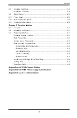
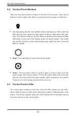
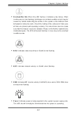
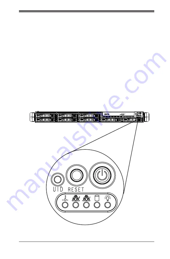
There are several LEDs on the control panel as well as others on the drive carriers 
to keep you constantly informed of the overall status of the system as well as the 

activity and health of specific components. Most SC113M models have three push-

buttons on the control panel: a UID button, a reset button and an on/off switch. This 
chapter covers these buttons, and explains the meanings of all LED indicators and 
the appropriate responses you may need to take. 

Figure 4-1: Chassis User Interface

Содержание CSE-113MFAC2-605CB

Страница 1: ...SC113M Chassis Series SC113MTQ 330CB SC113MTQ R400CB SC113MTQ 560CB SC113MTQ 563CB USER S MANUAL 1 0b SUPER...

Страница 2: ...ARDWARE SOFTWARE OR DATA STORED OR USED WITH THE PRODUCT INCLUDING THE COSTS OF REPAIRING REPLACING INTEGRATING INSTALLING OR RECOVERING SUCH HARDWARE SOFTWARE OR DATA Any disputes arising between man...

Страница 3: ...hingly short 20 deep chassis featuring advanced air flow thermal design for space limited applications With its short depth it efficiently packages eight hot swappable 2 5 SAS SATA hard drive bays int...

Страница 4: ...r details on this chassis model including the fans bays airflow shields and other components Chapter 4 System Interface This chapter provides details on the system interface which includes the functio...

Страница 5: ...abling at www supermicro com Appendix B Power Supply This chapter lists supported power supply information for the SC113M system Refer to our Web site for additional details at www supermicro com Appe...

Страница 6: ...3 Chassis Components 3 1 Overview 3 1 3 2 Components 3 1 Chassis 3 1 Backplane 3 1 Fans 3 1 Power Supply 3 2 Air Shroud 3 2 3 3 Where to get Replacement Components 3 2 Chapter 4 System Interface 4 1 O...

Страница 7: ...Preparing for Setup 6 1 Choosing a Setup Location 6 1 Rack Precautions 6 2 General Server Precautions 6 2 Rack Mounting Considerations 6 3 Ambient Operating Temperature 6 3 Reduced Airflow 6 3 Mechan...

Страница 8: ...SC113M Chassis Manual viii Notes...

Страница 9: ...2 5 SAS SATA hard drive bays Only enterprise level hard drives are recommended for use in Supermicro chassis The SC113M chassis includes one 330W Gold Level or a 560W Gold Level high efficiency power...

Страница 10: ...ress Super Micro Computer B V Het Sterrenbeeld 28 5215 ML s Hertogenbosch The Netherlands Tel 31 0 73 6400390 Fax 31 0 73 6416525 Email sales supermicro nl General Information support supermicro nl Te...

Страница 11: ...must be mailed when service is complete For faster service RMA authorizations may be requested online http www supermicro com support rma Whenever possible repack the chassis in the original Supermicr...

Страница 12: ...SC113M Chassis Manual 1 4 Notes...

Страница 13: ...ile a damage claim with carrier who delivered your system Decide on a suitable location for the rack unit that will hold that chassis It should be situated in a clean dust free area that is well venti...

Страница 14: ...em When working around exposed electrical circuits another person who is fa miliar with the power off controls should be nearby to switch off the power if necessary Use only one hand when working with...

Страница 15: ...neckties and unbuttoned shirt sleeves which can come into contact with electrical circuits or be pulled into a cooling fan Remove any jewelry or metal objects from your body which are excellent metal...

Страница 16: ...to contact with your clothing which may retain a charge even if you are wearing a wrist strap Handle a board by its edges only do not touch its components peripheral chips memory modules or contacts W...

Страница 17: ...com This chassis accepts a 1U backplane four fans with an optional fifth fan and one or two power supplies SC113M models come in black Backplane Each SC113M chassis comes with a 1U SAS SATA backplane...

Страница 18: ...re shields usually plastic that channel air directly to where it is needed Always use the air shroud included with your chassis 3 3 Where to get Replacement Components Although not frequently you may...

Страница 19: ...formed of the overall status of the system as well as the activity and health of specific components Most SC113M models have three push buttons on the control panel a UID button a reset button and an...

Страница 20: ...ndicates when illuminated and any corrective action you may need to take Reset The reset button is used to reboot the system 4 2 Control Panel Buttons There are three push buttons located on the front...

Страница 21: ...2 when flashing Overheat Fan Fail When this LED flashes it indicates a fan failure When continuously on not flashing it indicates an overheat condition which may be caused by cables obstructing the ai...

Страница 22: ...drive carrier has a green LED When illuminated this green LED on the front of the SATA drive carrier indicates drive activity A connection to the SATA backplane enables this LED to blink on and off w...

Страница 23: ...2 Installation The following sections will provide you with information on installing components and performing general mainenance on the system Installation Removing the Chassis Cover Installing Har...

Страница 24: ...the cover toward the rear of the chassis 2 Lift the cover upwards and off of the chassis Warning Except for short periods of time do NOT operate the server without the cover in place The chassis cove...

Страница 25: ...t hot swappable 2 5 hard drives Only SAS or enterprise HDDs are recommended Removing Hard Drive Trays from the Chassis 1 Press the release button on the drive carrier This extends the drive bay handle...

Страница 26: ...of both line up Note that there are holes in the carrier marked SATA to aid in correct installation 3 Secure the drive to the carrier with four screws as illustrated below 4 Insert the drive carrier i...

Страница 27: ...r B 3 Secure the DVD ROM drive to the floor of the drive carrier using one screw C as illustrated 4 Secure the left side of the DVD ROM drive by inserting screws D through the drive carrier and into t...

Страница 28: ...e chassis b Secure the screw with the hexagon nut rounded side up 4 Lay the motherboard on the chassis aligning the permanent and optional standoffs 5 Secure the motherboard to the chassis using the r...

Страница 29: ...he rounded Phillips head screws included in the SC113M accessories packaging Some motherboards require additional screws for heatsinks general components and or non standard security Optional standoff...

Страница 30: ...oud does not require screws to set up Installing the Air Shroud 1 Lay the chassis on a flat stable surface and remove the chassis cover 2 If necessary move any cables that interfere with the air shrou...

Страница 31: ...arts 3 Make sure no wires or foreign objects obstruct air flow through the chassis Pull all excess cabling out of the airflow path or use shorter cables The control panel LEDs inform you of system sta...

Страница 32: ...th the chassis open 2 Turn off the power to the system and unplug the system from the outlet 3 Remove the failed fan s power cord from the motherboard 4 Remove the screws securing the fan tray to the...

Страница 33: ...5 11 Chapter 5 Chassis Setup and Maintenance Figure 5 8 Installing the Fan Tray into the Chassis Figure 5 9 Fan Tray Secured to the Chassis...

Страница 34: ...the two screws A located on the cover of the power supply bay Set the screws aside for later use 3 Remove the two screws B located on the side of the power supply bay and set them aside for later use...

Страница 35: ...ing down the server Changing a 400 Watt Redundant Power Supply 1 Press the release button on the failed power supply 2 Use the handle to gently slide the power supply out the back of the chassis 3 Rep...

Страница 36: ...ystem fans In order to change jumper settings on the backplane it may be necessary to remove the backplane from the chassis Removing the Backplane from the Chassis 1 Power down and unplug the system f...

Страница 37: ...wer the backplane into the chassis sliding it into the clips on the floor of the chassis and aligning the mounting holes in the backplane with the mounting holes in the chassis 2 Secure the backplane...

Страница 38: ...SC113M Chassis Manual 5 16 Notes...

Страница 39: ...noise and electromagnetic fields are generated You will also need it placed near a grounded power outlet Be sure to read the Rack and Server Pre cautions in the next section 6 3 Preparing for Setup T...

Страница 40: ...General Server Precautions Review the electrical and general safety precautions that came with the com ponents you are adding to your chassis Determine the placement of each component in the rack befo...

Страница 41: ...mised Mechanical Loading Equipment should be mounted into a rack so that a hazardous condition does not arise due to uneven mechanical loading Circuit Overloading Consideration should be given to the...

Страница 42: ...cludes two rack rail assemblies in the rack mounting kit Each assembly consists of two sections an inner fixed chassis rail that secures directly to the server chassis and an outer fixed rack rail tha...

Страница 43: ...ize the chassis within the rack If you are not using a rack you do not have to install the inner rail extensions Installing the Inner Rails 1 Place the inner rack extensions on the side of the chassis...

Страница 44: ...ns with the slides Also both bracket ends must face the same direction 2 Adjust both the short and long brackets to the proper distance so that the rail fits snugly into the rack 3 Secure the long bra...

Страница 45: ...n the rack 2 Line chassis rails with the front of the rack rails 3 Slide the chassis rails into the rack rails keeping the pressure even on both sides It may be necessary to depress the locking tabs w...

Страница 46: ...hassis will extend out the front of the rack Larger chassis should be positioned to balance the weight between front and back If a bezel is included on your server remove it 3 Attach the two front bra...

Страница 47: ...es refer to the manufacturer of the motherboard you are using and our Web site at www supermicro com A 2 Cables Included with SC113M Chassis SC113MTQ 560CB Part Type Length Description CBL 0157L Round...

Страница 48: ...ly Description This cable has one SFF 8484 32 pin connector on one end and four SAS connectors seven pins each at the other This cable connects from the host motherboard or other controller to the bac...

Страница 49: ...20 pin CBL 0059 7 9 20 cm 8 pin CBL 0062 7 9 20 cm 4 pin CBL 0060 7 9 20 cm Front Panel to the Motherboard The SC113M chassis includes a cable to connect the chassis front panel to the motherboard If...

Страница 50: ...SC113M Chassis Manual A 4 Notes...

Страница 51: ...assis system SC113MTQ 563CB 560W Gold Level MFR Part PWS 563 1H Rated AC Voltage 100 240 V 50 60 Hz 7 5 Amp max 5V standby 3 Amp 12V 46 Amp 100 180V 49 Amp 180 240V 5V 18 Amp 3 3V 15 Amp 12V 0 5 Amp S...

Страница 52: ...60 Hz 4 5 Amp max 5V standby 3 Amp 12V 27 Amp 100 180Vac 31 Amp 180 240 Vac 5V 18 Amp 3 3V 15 Amp 12V 0 5 Amp SC113MTQ R400CB 400W MFR Part PWS 406P 1R AC Input 100 240 V 50 60 Hz 6 3 Amp DC Output 5...

Страница 53: ...scharge Touch a grounded metal object before removing a component from the antistatic bag Handle the backplane by its edges only do not touch its components peripheral chips memory modules or gold con...

Страница 54: ...shown in this manual C 4 Introduction to the SAS 113M Backplane The SAS 113M backplane has been designed to utilize the most up to date technol ogy available providing your system with reliable high q...

Страница 55: ...RST UPGRADE C 5 Front Connectors and Jumpers Front Connectors and Jumpers 1 Power Connectors 4 pin JP10 JP13 2 Upgrade Pin JP46 3 MG9072 Chip 4 Sideband 1 JP51 5 Sideband 2 JP52 6 I2 C Connector 1 JP4...

Страница 56: ...7 SCLOCK SCL SB0 10 No Connection 9 No Connection 3 MG9072 Chip The MG9072 is an enclosure management chip that supports the SES 2 controller and SES 2 protocols C 6 Front Connector and Pin Definition...

Страница 57: ...P45 are used to monitor HDD activity and status See the table on the right for pin definitions I2 C Connector Pin Definitions Pin Definition 1 Data 2 Ground 3 Clock 4 No Connection 8 MG9072 Reset Allo...

Страница 58: ...e connector Pin 1 is identified with a square solder pad on the printed circuit board Note On two pin jumpers Closed means the jumper is on and Open means the jumper is off the pins Connector Pins Jum...

Страница 59: ...Jumper Setting SGPIO Jumper Setting Note JP33 2 3 1 2 Controller ID C98 C6 C5 C4 C285 C137 JP29 R259 JP33 JP45 JP44 JP46 U18 JP10 JP13 JP51 JP52 J16 J14 J5 J7 J6 J12 J8 J10 MH6 MH5 MH3 MH4 MH2 MH1 64...

Страница 60: ...SAS SATA HDD 5 SAS SATA 6 J13 SAS SATA HDD 6 SAS SATA 7 J15 SAS SATA HDD 7 SAS 7 SAS 6 SAS 4 SAS 0 Rear LED Indicators Rear Connector Hard Drive Activity Failure LED SAS SATA 0 D12 D5 SAS SATA 1 D13...

Страница 61: ...C 9 Appendix C SAS 113TQ Backplane Specifications Notes...

Страница 62: ...sonably expected to result in significant injury or loss of life or catastrophic property damage Accordingly Supermicro disclaims any and all liability and should buyer use or sell such products for u...

Отзывы: