


62
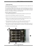
A+ Server AS -4124GO-NART/AS -4124GO-NART+ User's Manual
Chapter 4
Motherboard Connections
This section describes the connections on the motherboard and provides pinout definitions.
Note that depending on how the system is configured, not all connections are required.
The LEDs on the motherboard are also described here. A motherboard layout indicating
component locations may be found in Chapter 1.
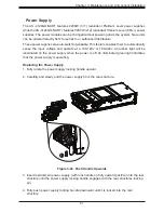
Please review the Safety Precautions in Chapter 3 before installing or removing components.
4.1 Headers and Connectors
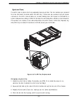
Fan Headers
There are eight fan headers on the motherboard. These are 4-pin fan headers; pins 1-3 are
backward compatible with traditional 3-pin fans. The onboard fan speeds are controlled by
Fan Mode in the BMC. When using Fan Mode setting, please use all 4-pin fans.
Fan Header
Pin Definitions
Pin#
Definition
1
Ground (Black)
2
+12V (Red)
3
Tachometer (Yellow)
4
PWM control (Blue)
IPMB System Management Bus Header
A System Management Bus header for IPMI 2.0 is located at JIPMB1. Connect the appropriate
cable here to use the IPMB I
2
C connection on your system.
IPMB Header
Pin Definitions
Pin#
Definition
1
Data
2
Ground
3
Clock
4
No Connection
Содержание A+
Страница 1: ...USER S MANUAL Revision 1 0b A Server AS 4124GO NART AS 4124GO NART ...
Страница 13: ...13 Chapter 1 Introduction 1 5 System Architecture Block Diagrams Figure 1 5 System Block Diagram ...
Страница 14: ...14 A Server AS 4124GO NART AS 4124GO NART User s Manual Figure 1 6 Motherboard Block Diagram ...
Страница 95: ...Chapter 4 UEFI BIOS 95 Save Changes and Exit Use this item to save the changes above and exit ...