Supermicro 7044H-32R Скачать руководство пользователя страница 122

B-28

S

UPER

S

ERVER 7044H-32R User's Manual

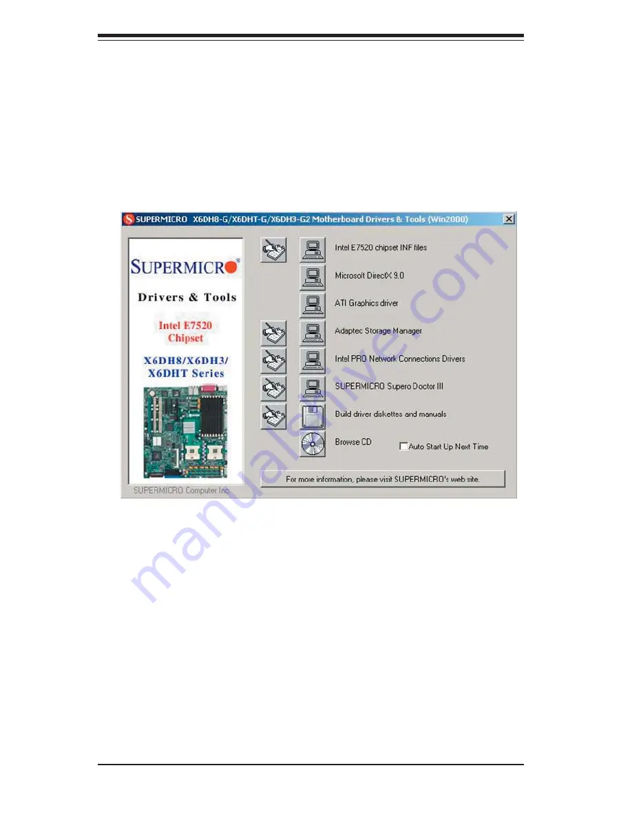
Driver/Tool Installation Display Screen

(*Note: Click the icons showing a hand writing on paper to view the readme fi les 

for each item.  Click the computer icons to the right of these items to install each 

item (from top to the bottom) one at a time.  

After installing each item, you must 

re-boot the system before moving on to the next item on the list.

  You should 

install everything here except for the Supero Doctor utility, Intel LDCM  and the 

LAN/SCSI driver diskettes, which are optional.   The bottom icon with a CD on it 

allows you to view the entire contents of the CD. ) 

(*Please refer to the Adaptec User's Guide for the installation of Adaptec's 

Serial ATA RAID Controller Driver. Adaptec's User's Guide is included in the 

CD. You can also download a copy of the user's guide from our web site.)

B-3  Installing Other Software Programs and Drivers

A. Installing Drivers other than Adaptec Embedded Serial 
ATA RAID Controller Driver

After you've installed Windows Operating System, a screen as shown below will 

appear. You are ready to install software programs and  drivers that have not yet 

been installed. To install these software programs and  drivers, click the icons to 

the right of these items.

Содержание 7044H-32R

Страница 1: ...SUPERSERVER 7044H 32R SUPER USER S MANUAL 1 0...

Страница 2: ...R INABILITY TO USE THIS PRODUCT OR DOCUMENTATION EVEN IF ADVISED OF THE POSSIBILITY OF SUCH DAMAGES IN PARTICULAR THE VENDOR SHALL NOT HAVE LIABILITY FOR ANY HARDWARE SOFTWARE OR DATA STORED OR USED W...

Страница 3: ...duction The rst chapter provides a checklist of the main components included with the server system and describes the main features of the X6DH3 G2 serverboard and the SC743T R760 chassis which compri...

Страница 4: ...o this chapter when adding or removing processors or main memory and when recon g uring the serverboard Chapter 6 Advanced Chassis Setup Refer to Chapter 6 for detailed information on the SC743T R760...

Страница 5: ...v Preface Notes...

Страница 6: ...ng the System into a Rack 2 4 2 5 Checking the Serverboard Setup 2 8 2 6 Checking the Drive Bay Setup 2 9 Chapter 3 System Interface 3 1 Overview 3 1 3 2 Control Panel Buttons 3 1 Power 3 1 Reset 3 1...

Страница 7: ...onnector De nitions 5 11 ATX Power Connection 5 11 PWR_SEC Connection 5 11 Processor Power Connector 5 11 NMI Button 5 11 Power LED 5 11 HDD LED 5 12 NIC1 LED 5 12 NIC2 LED 5 12 Overheat Fan Fail LED...

Страница 8: ...ve Connections 5 21 Parallel Port Connector 5 21 Floppy Connector 5 22 IDE Connectors 5 23 Chapter 6 Advanced Chassis Setup 6 1 Static Sensitive Devices 6 1 6 2 Front Control Panel 6 3 6 3 System Fans...

Страница 9: ...Table of Contents ix Appendices Appendix A BIOS POST Codes A 1 Appendix B Software Installation B 1 Appendix C System Speci cations C 1...

Страница 10: ...Notes x SUPERSERVER 7044H 32R User s Manual...

Страница 11: ...ious hardware components have been included with the SuperServer 7044H 32R as listed below Four 4 8 cm hot swap chassis fans FAN 0072 Two 2 8 cm hot swap rear exhaust fans FAN 0081 One 1 air shroud CS...

Страница 12: ...0W controller is integrated into the X6DH3 G2 to provide an eight port Serial Attached SCSI SAS Serial ATA subsystem which is RAID 0 and 1 supported The 6300ESB South Bridge of the chipset also includ...

Страница 13: ...auto switching voltage regulators chassis and CPU overheat sensors virus protection and BIOS rescue 1 3 Server Chassis Features The following is a general outline of the main features of the SC743T R...

Страница 14: ...4U rackmount con guration The I O backplane provides six motherboard ex pansion slots one COM port a parallel port a VGA port two USB 2 0 ports PS 2 mouse and keyboard ports and two gigabit Ethernet...

Страница 15: ...A 100 UDMA 100 IDE IDE PRI SEC PRI SEC A PXH 1 PXH 1 B SAS SAS HC2_8Ports HC2_8Ports PCIX BUS 100 MHZ PCIX BUS 100 MHZ PCIX BUS 133 MHZ PCIX BUS 133 MHZ 1 5V 1 5V 3 3V 3 3V DDR266 DDR266 DDR333 DDR333...

Страница 16: ...ope Address SuperMicro Computer B V Het Sterrenbeeld 28 5215 ML s Hertogenbosch The Netherlands Tel 31 0 73 6400390 Fax 31 0 73 6416525 Email sales supermicro nl General Information support supermicro...

Страница 17: ...to Section 2 5 2 2 Unpacking the System You should inspect the box the system was shipped in and note if it was damaged in any way If the server itself shows damage you should le a damage claim with t...

Страница 18: ...be coupled together Always make sure the rack is stable before extending a component from the rack You should extend only one component at a time extending two or more simul taneously may cause the r...

Страница 19: ...mised Mechanical Loading Equipment should be mounted into a rack so that a hazardous condition does not arise due to uneven mechanical loading Circuit Overloading Consideration should be given to the...

Страница 20: ...ame with the rack unit you are using Identifying the Sections of the Rack Rails The optional rackmount kit CSE PT26 or CSE PT26B black includes two rack rail assemblies Each of these assemblies consis...

Страница 21: ...hassis rail sections you just removed along the side of the chassis making sure the screw holes line up Note that these two rails are left right speci c Screw the rail securely to the side of the chas...

Страница 22: ...xed rack rail sliding rail guide assemblies at the desired location in the rack keeping the sliding rail guide facing the inside of the rack Screw the assembly securely to the rack using the brackets...

Страница 23: ...hese rst keeping in mind that they are left right speci c marked with L and R Then line up the rear of the chassis rails with the front of the rack rails Slide the chassis rails into the rack rails ke...

Страница 24: ...access to the inside of the server 2 Check the CPUs processors You may have one or two processors already installed into the serverboard Each processor should have its own heatsink attached See Chapt...

Страница 25: ...need to remove the top left chassis cover The SAS SATA disk drives can be installed and removed from the front of the chassis without removing any chassis covers 2 Installing components into the 5 25...

Страница 26: ...ut was carefully designed to promote suf cient air ow through the chassis Also note that all power and data cables have been routed in such a way that they do not block the air ow generated by the fan...

Страница 27: ...d the activity and health of speci c components 3 2 Control Panel Buttons There are two push buttons located on the front of the chassis These are in order from left to right a power on off button and...

Страница 28: ...32R this LED indicates SAS SATA drive activity when ashing NIC1 Indicates network activity on JLAN1 when ashing NIC2 Indicates network activity on JLAN2 when ashing Overheat Fan Fail When this LED ash...

Страница 29: ...to Chapter 6 for details on replacing the power supply This LED should be off when the system is operating normally 3 4 SAS SATA Drive Carrier LED Each SAS SATA drive carrier has a green LED When illu...

Страница 30: ...3 4 SUPERSERVER 7044H 32R User s Manual Notes...

Страница 31: ...rd memory modules and the CD ROM and oppy drives When disconnecting power you should rst power down the system with the operating system and then unplug the power cords of all the power supply units i...

Страница 32: ...and unbuttoned shirt sleeves which can come into contact with electrical circuits or be pulled into a cooling fan Remove any jewelry or metal objects from your body which are excellent metal conductor...

Страница 33: ...se Touch a grounded metal object before removing the board from the antistatic bag Do not let components or PCBs come into contact with your clothing which may retain a charge even if you are wearing...

Страница 34: ...hat the chassis cover is in place when the 7044H 32R is operating to assure proper cooling Out of warranty damage to the 7044H 32R system can occur if this practice is not strictly followed Figure 4 1...

Страница 35: ...at the size and weight of the serverboard can cause it to bend if handled improperly which may result in damage To prevent the serverboard from bending keep one hand under the center of the board to s...

Страница 36: ...pin processors If install ing one processor only install it into CPU socket 1 5 2 Processor and Heatsink Installation When handling the processor package avoid placing direct pressure on the label are...

Страница 37: ...er is only partly raised damage to the socket or CPU may result 5 Screw in two diagonal screws until just snug do not fully tighten then do the same with the remaining two diagonal screws Finish by fu...

Страница 38: ...connect to the pin 1 locations If you are con guring the system keep the air ow in mind when routing the cables The following data cables with their serverboard connector locations noted should be con...

Страница 39: ...e sides of each header All JF1 wires have been bundled into single keyed ribbon cable to simplify their connection The red wire in the ribbon cable plugs into pin 1 of JF1 Connect the other end of the...

Страница 40: ...nstalling or removing DIMM modules to prevent any possible damage Also note that the memory is inter leaved to improve performance see step 1 DIMM Installation See Figure 5 5 1 Insert the desired numb...

Страница 41: ...to 16 GB of registered ECC DDR2 400 SDRAM You should not mix DIMMs of different sizes and speeds See Figure 5 5 for installing and removing memory modules To Install Insert module vertically and pres...

Страница 42: ...eded 2 PCI card installation Before installing a PCI add on card make sure you install it into a slot that supports the speed of the card see step 1 above Begin by removing the screw from the PCI slot...

Страница 43: ...J6 J12 JP9 VGA COM1 FAN6 FAN5 J38 ATX PWR JPW1 JPG1 Slot 3 PCI X 100MHz ZCR Slot 2 PCI X 100MHz Slot 1 PCI 32 JPL1 Battery FAN3 IPMI1 FAN8 JBT1 FAN1 J1D1 Slot 5 PCI E 8x JL1 JP13 JOH PXH JLAN1 FAN2 W...

Страница 44: ...aders IPMI IPMI 2 0 Socket J1D1 Processor Power Connector J5 J6 IDE 1 2 Hard Disk Drive Connectors J12 Floppy Disk Drive Connector J32 SMB System Management Bus Header J33 Keyboard Mouse Ports J38 Sec...

Страница 45: ...12v 8 pin J15 connector J38 must also be connected to your power sup ply See the table on the right for pin de nitions NMI Button Pin De nitions JF1 Pin De nition 19 Control 20 Ground Processor Power...

Страница 46: ...plies to systems with redundant power supplies such as the 7044H 32R NIC2 LED The NIC2 Network Interface Control ler LED connection is located on pins 9 and 10 of JF1 Attach the NIC2 LED cable to disp...

Страница 47: ...st 4 seconds Refer to the table on the right for pin de nitions Universal Serial Bus USB0 1 Two Universal Serial Bus ports are located beside the PS 2 keyboard mouse ports USB0 is the bottom connector...

Страница 48: ...ard layout for location See the table on the right for pin de nitions Note Pin 10 is included on the header but not on the port NC indicates no connection Serial Port Pin De nitions COM1 COM2 Pin De n...

Страница 49: ...VCC 5 Clock 6 NC Speaker Connector Pin De nitions JD1 Pin Function De nition 4 Speaker data red wire 5 Key No connection 6 Key 7 Speaker data Extra Universal Serial Bus Headers Two additional USB head...

Страница 50: ...OR card and cable to use this feature SMB The System Management Bus header for the PCI bus designated J11 is located near the battery Connect the appropriate cable here to utilize SMB on your system S...

Страница 51: ...ar CMOS and will also clear any passwords Instead of pins this jumper consists of contact pads to prevent accidentally clearing the contents of CMOS To clear CMOS 1 First power down the system and unp...

Страница 52: ...table on the right for jumper settings Watch Dog must also be enabled in BIOS Note When enabled the user needs to write their own application software in order to disable the Watch Dog Timer JLAN Enab...

Страница 53: ...ition Open Disabled Closed Enabled Alarm Reset JAR The system will notify you in the event of a power supply failure This feature assumes that Supermicro redundant power supply units are installed in...

Страница 54: ...D indicators DS1 DS8 indicate the activity status of SAS ports 0 7 See the table on the right for pin de nitions SAS Activity LED Indicators DS9 DS16 DS De nition DS De nition DS1 SAS0 Act DS5 SAS4 Ac...

Страница 55: ...isk drives The connector with twisted wires always connects to drive A and the connector that does not have twisted wires always connects to drive B Parallel Port Connector See the table below for pin...

Страница 56: ...n De nition 1 Ground 2 FDHDIN 3 Ground 4 Reserved 5 Key 6 FDEDIN 7 Ground 8 Index 9 Ground 10 Motor Enable 11 Ground 12 Drive Select B 13 Ground 14 Drive Select B 15 Ground 16 Motor Enable 17 Ground 1...

Страница 57: ...ost Data 7 4 Host Data 8 5 Host Data 6 6 Host Data 9 7 Host Data 5 8 Host Data 10 9 Host Data 4 10 Host Data 11 11 Host Data 3 12 Host Data 12 13 Host Data 2 14 Host Data 13 15 Host Data 1 16 Host Dat...

Страница 58: ...5 24 SUPERSERVER 7044H 32R User s Manual Notes...

Страница 59: ...rtant to handle them very carefully The following measures are generally suf cient to protect your equipment from static discharge Precautions Use a grounded wrist strap designed to prevent static dis...

Страница 60: ...6 2 SUPERSERVER 7044H 32R User s Manual 8 SAS SATA Drive Bays behind locking bezel Figure 6 1 Chassis Front View System Reset Main Power System LEDs Floppy Drive 5 25 Drive Bays 2 USB Ports...

Страница 61: ...over to the control panel side of the chassis The LEDs on the control panel inform you of system status see Figure 6 2 for details See Chapter 5 for details on JF1 Figure 6 2 Front Control Panel LEDs...

Страница 62: ...ls on removing the cover 2 Removing a hot plug fan housing Depress the locking tab on a chassis cooling fan and pull the unit straight out by the handle see Figure 6 3 The fan wiring for these fans ha...

Страница 63: ...Chapter 6 Advanced Chassis Setup 6 5 Figure 6 4 Removing the Air Shroud Figure 6 3 Removing a Chassis Fan...

Страница 64: ...If you need to add a new SAS SATA drive insert the drive into the carrier with the printed circuit board side facing down so that the mounting holes align with those in the carrier Secure the drive to...

Страница 65: ...A Drive Carrier 3 SAS SATA backplane The SAS SATA drives plug into an SAS SATA backplane A ribbon cable from JA1 on the motherboard should be connected to the JP26 connector on the SAS SATA backplane...

Страница 66: ...Then slide the CD ROM into the bay and secure it to the chassis with the drive carrier screws you rst removed Attach the power and data cables to the drive Replace the top left chassis cover before r...

Страница 67: ...ing the Power Supply You do not need to shut down the system to replace a power supply unit The re dundant feature will keep the system up and running while you replace the failed hot swap unit Replac...

Страница 68: ...6 10 SUPERSERVER 7044H 32R User s Manual Notes...

Страница 69: ...cal power When the computer is turned off a backup battery provides power to the BIOS ash chip enabling it to retain system parameters Each time the computer is powered on the computer is con gured wi...

Страница 70: ...fter turning the system on or 2 When the message shown below appears brie y at the bottom of the screen during the POST Power On Self Test press the Delete key to activate the main Setup menu Press th...

Страница 71: ...the correct data Press the Enter key to save the data BIOS Date This feature allows BIOS to automatically display the BIOS date Legacy Diskette A This setting allows the user to set the type of oppy d...

Страница 72: ...sub menu are Type Selects the type of IDE hard drive The options are Auto which allows BIOS to automatically determine the hard drive s capacity number of heads etc a number from 1 39 to select a pre...

Страница 73: ...will access the IDE Channel 0 Master Device via the LBA mode The options are Enabled and Disabled 32 Bit I O This option allows the user to enable or disable the function of 32 bit data transfer The o...

Страница 74: ...BIOS Setup options are described in this section Boot Features Access the submenu to make changes to the following settings QuickBoot Mode If enabled this feature will speed up the POST Power On Self...

Страница 75: ...che Cache System BIOS Area This setting allows you to designate a reserve area in the system memory to be used as a System BIOS buffer to allow the BIOS write cache its data into this reserved memory...

Страница 76: ...the buffer without writing data to the System Memory for fast CPU data processing and operation The options are Uncached Write Through Write Protect and Write Back Cache Extended Memory If enabled thi...

Страница 77: ...0MHz ZCR Slot 3 PCI X 133MHz Slot 4 PCI Exp X8 Slot 5 PCI Exp X8 Slot 6 Access the submenu for each of the settings above to make changes to the following Option ROM Scan When enabled this setting wil...

Страница 78: ...ll attempt to decrease the interference whenever needed The options are Enabled and Disabled Memory Remap Function Control Select Enabled to re allocate memory resource for PCI slots The options are E...

Страница 79: ...Set to Enabled to allow the operating system to debug a system crash after a reset The options are Disabled and Enabled No Execute Mode Memory Protection Enable this feature to enable the functionali...

Страница 80: ...I O Device Con guration Access the submenu to make changes to the following settings KBC Clock input This setting allows you to set the clock frequency for the Keyboard Clock The options are 6MHz 8MHz...

Страница 81: ...s are 378 278 and 3BC Interrupt Select the IRQ interrupt request for the parallel port The options are IRQ5 and IRQ7 Mode This feature allows you to specify the parallel port mode The options are Outp...

Страница 82: ...t log capacity It is not a setting View DMI Event Log Highlight this item and press Enter to view the contents of the event log Event Logging This setting allows you to Enable or Disable event logging...

Страница 83: ...Console Type This item allows you to choose from the available options to select the console type for console redirection The options are VT100 VT100 8bit PC ANSI 7bit PC ANSI VT100 VT UTF8 Flow Cont...

Страница 84: ...If the option is set to 4 pin the fan speed will be controlled by the Thermal Management Settings pre con gured by the user at this feature Select 3 pin if your chassis came with 3 pin fan headers Se...

Страница 85: ...ssword has been entered for the system User Password Is This displays whether a user password has been entered for the system Clear means such a password has not been used and Set means a user passwor...

Страница 86: ...arrow keys You should see the following display Highlighting a setting with a or will expand or collapse that entry See details on how to change the order and specs of boot devices in the Item Speci c...

Страница 87: ...Discarding Changes Highlight this item and hit Enter to exit the BIOS Setup utility without saving any changes you may have made Load Setup Defaults Highlight this item and hit Enter to load the defau...

Страница 88: ...7 20 SUPERSERVER 7044H 32R User s Manual Notes...

Страница 89: ...attempt to initialize video and write the error in the top left corner of the screen The following is a list of codes that may be written to port 80h Appendix A BIOS POST Codes POST Code Description 0...

Страница 90: ...h Shadow system BIOS ROM 3Ah Auto size cache 3Ch Advanced con guration of chipset registers 3Dh Load alternate registers with CMOS values 41h Initialize extended memory for RomPilot 42h Initialize int...

Страница 91: ...t 80h Disable onboard Super I O ports and IRQs 81h Late POST device initialization 82h Detect and install external RS232 ports 83h Con gure non MCD IDE controllers 84h Detect and install external para...

Страница 92: ...e QuietBoot optional B6h Check password optional B7h Initialize ACPI BIOS B9h Prepare Boot BAh Initialize SMBIOS BBh Initialize PnP Option ROMs BCh Clear parity checkers BDh Display MultiBoot menu BEh...

Страница 93: ...ize EEh Shadow Boot Block EFh System memory test F0h Initialize interrupt vectors F1h Initialize Run Time Clock F2h Initialize video F3h Initialize System Management Manager F4h Output one beep F5h Cl...

Страница 94: ...A 6 SUPERSERVER 7044H 32R User sManual Notes...

Страница 95: ...ion the cables used in PATA can only extend to 40cm long while Serial ATA cables can extend up to one meter Overall Serial ATA provides better functionality than Parallel ATA Introduction to the Intel...

Страница 96: ...nd PATA to the Enhanced Mode The newer Operating Systems can accom modate both Enhanced Mode and Combined Mode and support up to 6 ATA devices Please refer to the Advanced Chipset Control under the Ad...

Страница 97: ...ect OK to con rm the selection Press the Enter key to load the default settings to the BIOS 3 Use the arrow keys to select the Main Menu in the BIOS 4 Scroll down to SATA RAID Enable and press the Ent...

Страница 98: ...ptec s RAID Driver Installation Instructions please refer to the Adaptec RAID Controller User s Guide Emb_SA_RAID_UG pdf in the CD that came with this motherboard You can also download a copy of Adapt...

Страница 99: ...ys Select this option to view array properties and delete arrays The following sec tions describe the operations Of Managing Arrays To select this option use the arrow keys and the enter key to select...

Страница 100: ...you delete it to prevent the loss of data Deleted arrays cannot be restored To delete an existing array 1 Turn on your computer and press Ctrl A when prompted to access the ARC utility 2 From the ARC...

Страница 101: ...n array 1 Turn on your computer and press Ctrl A when prompted to access the ARC utility 2 From the ARC menu select Array Con guration Utility Main Menu ACU as shown on the rst screen on page B 5 3 Fr...

Страница 102: ...annot change the array properties using the ACU You will need to use the Adaptec Storage Manager Browser Edition Refer to Adaptec s User s Guide in the enclosed CD To assign properties to the new arra...

Страница 103: ...o Init Creating a RAID 0 on new drives RAID 0 Migrate Note Creating a RAID 0 from one new drive and one drive with data you wish to preserve RAID 1 Build1 Any time you wish to create a RAID 1 but espe...

Страница 104: ...llows you to use drives of different sizes in a RAID However during a build operation only the smaller drive can be selected as the source or rst drive 5 When migrating from single volume to RAID 0 mi...

Страница 105: ...sterisk will appear next to the bootable array as shown in the picture below Deleting a Bootable Array To delete a bootable array 1 From the Main menu select Manage Arrays 2 From the List of Arrays se...

Страница 106: ...sk overwrites the partition table on the disk and makes any data on the disk inaccessible If the drive is used in an array you may not be able to use the array again Do not initialize a disk that is p...

Страница 107: ...Appendix B Software Installation B 13 4 Use the up and down arrow keys to select the disk you wish to initialize and press Insert as shown in the screen below...

Страница 108: ...ep 4 so that both drives to be initialized are selected as shown in the screen below 6 Press Enter 7 Read the warning message as shown in the screen 8 Make sure that you have selected the correct disk...

Страница 109: ...form a Rebuild to get the array to Optimal status For a criti cal array Rebuild operation the optimal drive is the source drive Note 2 If no spare array exists and a hard disk drive fails you need to...

Страница 110: ...OS please make sure that the Adapter WWN address is listed This is a 16 digit number If this number is not shown you will not be able to use the controller Once the WWN address is listed press the Ctr...

Страница 111: ...y Properties To view the properties of an existing array 1 At the BIOS prompt press Ctrl A 2 From the ARC menu select Array Con guration Utility ACU 3 From the ACU menu select Manage Arrays as shown o...

Страница 112: ...ll result in data loss Do you also want to delete the parti tion Yes No 6 Press Yes to delete the array or partition or No to return to the previous menu 7 Press Esc to return to the previous menu Cre...

Страница 113: ...following table gives examples of when each is appropriate Note If you select Migrate for RAID 0 or Build for RAID 1 you will be asked to select the source drive The contents of the source drive will...

Страница 114: ...1 From the Main menu select Manage Arrays 2 From the List of Arrays select the array you want to make bootable and press Ctrl B 3 Enter Y to create a bootable array when the following message is disp...

Страница 115: ...From the ARC menu select Array Con guration Utility ACU 3 Select Initialize Drives 4 Use the up and down arrow keys to highlight the disk you wish to initialize and press Insert 5 Repeat Step 4 so th...

Страница 116: ...ct Utility enables you to con gure SAS disk drive settings To access the SAS utilities 1 Turn on your computer and press Ctrl A when prompted to access the ARC util ity as shown in the screen below 2...

Страница 117: ...press F6 Note The default setting for each item is listed below Runtime BIOS Enabled BBS Support Device POST Banner Display Enabled CTRL A Message Display Enabled Physical Drives Display during POST E...

Страница 118: ...Utility and press Enter to access the Physical Con guration submenu as shown below 3 Select Physical Con guration and press Enter to access SAS Device Con guration submenu as shown below 4 Use the arr...

Страница 119: ...from the screen as shown above and press Enter 3 When the submenu appears select the desired disk and press Enter The following options are available 1 Format Disk Simulates a low level format of the...

Страница 120: ...n gurations press ESC to exit The following screen will appear 2 Press Yes to exit the Utility For more information regarding Adaptec RAID Utility please refer to Adaptec s User s Guide in the CD incl...

Страница 121: ...CD g Press the F6 key when the message Press F6 if you need to install a third party SCSI or RAID driver displays h When the Windows OS Setup screen appears press S to specify additional device s i I...

Страница 122: ...optional The bottom icon with a CD on it allows you to view the entire contents of the CD Please refer to the Adaptec User s Guide for the installation of Adaptec s Serial ATA RAID Controller Driver...

Страница 123: ...nt is called SD III Client The Supero Doctor III program included on the CDROM that came with your motherboard allows you to moni tor the environment and operations of your system Supero Doctor III di...

Страница 124: ...oaded from our Web site at ftp ftp supermicro com utility Supero_Doctor_III You can also download SDIII User s Guide at http www supermicro com PRODUCT Manuals SDIII UserGuide pdf For Linux we will st...

Страница 125: ...ECC DDR2 400 SDRAM Note Dual channel memory requires memory to be installed two modules at a time See the memory section in Chapter 5 for details SAS SATA Controller Adaptec 9410W controller for 8 po...

Страница 126: ...ud for tower 4U chassis System Input Requirements AC Input Voltage 100 240V AC auto range Rated Input Current 14A max Rated Input Frequency 50 to 60 Hz PFC Power Supply Rated Output Power 760W Model S...

Страница 127: ...ectromagnetic Immunity EN 55024 CISPR 24 EN 61000 4 2 EN 61000 4 3 EN 61000 4 4 EN 61000 4 5 EN 61000 4 6 EN 61000 4 8 EN 61000 4 11 Safety EN 60950 IEC 60950 Compliant UL Listed USA CUL Listed Canada...

Страница 128: ...C 4 SUPERSERVER 7044H 32R User s Manual Notes...

Отзывы: