Chapter 6: Advanced Chassis Setup
6-3
6-2
S
UPER
S
TORAGE
S
YSTEM 6038R-DE2CR16L User's Manual
fans. The counter-rotating action helps dampen vibration levels while generating
exceptional airflow.
It is very important that the chassis cover is properly installed and making a good
seal for the cooling air to circulate properly through the chassis and cool the com-
ponents.
System Fan Failure
Fan speed is controlled by system temperature via IPMI. If a fan fails, the remaining
fans will ramp up to full speed and the overheat/fan fail LED on the control panel
(of the same side as the failed fan) will turn on.
The fans may also be visually inspected for failure. Replace any failed fan at your
earliest convenience with the same type and model (the system can continue to run
with a failed fan). Remove the top chassis cover while the system is still running to
determine which of the fans has failed.
Replacing System Fans
Replace the failed fan with an identical 4-cm, 12-volt counter-rotating fan (p/n FAN-
0157L4, available from Supermicro). See Figures 6-2 and 6-3.
Replacing Fans
1. Shutdown the node with the failed fan(s) and remove the AC power cord.
2. On the node with the failed fan, push the release bar down to unlock the
serverboard tray.
3. Use the bar to pull the node/serverboard from the chassis.
4. Remove the failed fan from the assembly and replace it with an identical
replacement. You may need to remove the assembly to replace the lower fan.
5. Slide the serverboard tray back into the chassis. When seated, lift the release
bar to lock it into place.
6. Reconnect the AC power cord and power up the node.
7. Inspect the replaced fan to verify it is working.
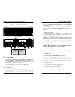
Figure 6-1. Front and Rear Chassis Views
6-2 Control Panel
The control panels are connected to the serverboards through the midplane. The
LEDs on the control panels are associated with the node on the same side of the
chassis. Note that only the right-side control panel includes a power button. De-
pressing this button will turn both nodes on or off.
See Chapter 3 for details on the LEDs and the control panel buttons.
6-3 System Fans
System cooling is provided by three sets of counter-rotating fans on each
serverboard as well as an assembly that holds three fans near the front of the node.
Each fan assembly (one for each node) consists of three sets of counter-rotating
Control Panel
Control Panel
Removable Drives (16)
1
1
2
2
3
3
4
4
5
5
6
6
Rear Chassis Features
1. Power Supply
4. KVM Connection
2. Fan Assembly
5. Dual SAS Ports
3. LAN Ports (1 Gb) 6. Add-on Card Slots
Содержание 6038R-DE2CR16L
Страница 1: ...USER S MANUAL 1 0a SUPER STORAGE SYSTEM 6038R DE2CR16L ...
Страница 6: ...SUPERSTORAGESYSTEM 6038R DE2CR16L User s Manual x Notes ...
Страница 17: ...3 4 SUPERSTORAGESYSTEM 6038R DE2CR16L User s Manual Notes ...
Страница 45: ...6 10 SUPERSTORAGESYSTEM 6038R DE2CR16L User s Manual Notes ...
Страница 69: ...A 2 SUPERSTORAGESYSTEM 6038R DE2CR16L User s Manual Notes ...

