


15
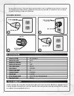
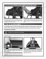
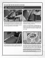
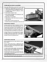
PROPER ABRASIVE WRAP POSITION
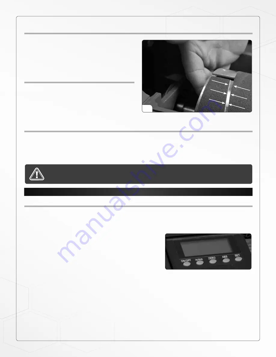
Position the abrasive wrap in the slot with sufficient
room between the inside of the slot and the tapered
end of the wrap to allow it to be pulled into the drum
as needed (see opposite picture). If enough space is
not left between the wrap and the inside of the slot the
take-up fastener will not operate properly.
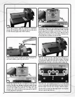
ABRASIVE WRAP TENSION ADJUSTMENT
The abrasive wrap may stretch enough in use to allow
the take-up lever to reach its lowest position. If this oc-
curs then tension is not longer maintained on the abra-
sive wrap. To fix this reset the take-up lever by raising
it, pushing the abrasive wrap into the slot and then re-
leasing the clip lever.
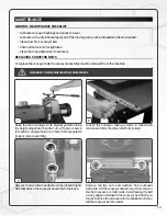
MAXIMIZING ABRASIVE LONGEVITY
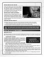
A sandpaper cleaning stick may be used to remove deposits and help extend the life of the abrasive.
1.
To use the cleaning stick, operate the sanding drum with the dust cover open and dust collection on.
2.
Hold the cleaning stick against the rotating drum and move it along the drum surface.
3.
Use a shop brush to remove any cleaning stick remnants from the drums before resuming sanding operations.
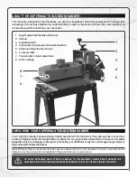
OPERATING THE 16-32 DRUM SANDER
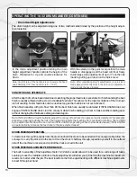
DRUM DEPTH OF CUT
Determining the depth of cut is the most important operating procedure decision. It may take some experimenta-
tion to determine the proper depth of cut. We recommend practicing on a scrap of wood prior to sanding a project.
•
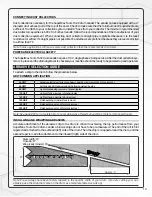
Digital Read-Out Operation
For added convenience a digital read out (DRO) for sanding thickness
is included as standard equipment with this unit. A DRO offers the
most precise reading of sanded thickness and allows for accurate re-
peatability of a thickness. This is great when making parts that must
be an exact thickness or when matching a thickness.
1.
To operate, press the ON/OFF button and then use the IN/MM
button to select between the standard inch or metric millimeter
settings – the inches setting shows readings in both decimal places and fractions.
2.
With abrasive installed, lower the drum until it touches the conveyor belt. Then press and hold the “ZERO” but-
ton to calibrate the DRO to absolute zero. The DRO is now set to read sanding thickness.
3.
The ABS button selects between Absolute (ABS) or Incremental (INC) modes. ABS mode is used to read the
actual thickness of the workpiece. INC mode is used to measure the amount of material removed from the
piece’s original thickness – it will read as a negative number. When switching back from INC to ABS the unit will
once again take its reading from absolute zero as calibrated in step 2.
4.
The SET button allows selection in inches mode from either 1/32", 1/64", or 1/128' depending on the level of
precision required.
FOR YOUR OWN SAFETY ALWAYS WEAR EYE PROTECTION WHILE PERFORMING ABRASIVE CLEANING
AND TAKE ALL PRECAUTIONS TO AVOID ANY CONTACT WITH HANDS OR CLOTHING ON THE UNCOVERED.
5
Содержание 16-32
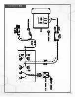
Страница 23: ...23 16 32 WIRING DIAGRAM...
Страница 26: ...16 32 HEAD ASSEMBLY 26...
Страница 29: ...NOTES 29...
Страница 30: ...P 1 888 454 3401 F 1 651 454 3465 SuperMaxTools com sales SuperMaxTools com...


