background image

8. Mounting Connecting Arms to Carriage and Door

8.1 Close the Garage Door with the Carriage disengaged.
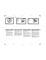
8.2 Attach the Bent Connecting Arm to the Door Mounting

Bracket using the Clevis Pin provided. (Fig.7)

8.3 Bring the Straight and Bent Connecting Arms together

and align the 2 closest sets of holes.

8.4 Using 2 of the 8 mm bolts and nuts provided, securely

fix the Bent and Straight Connecting Arms together.

9. Disengaging the Garage Door

9.1 To disengage the AGDO from the Garage Door, pull down on the disengage chord. (Fig.8)
9.2 The rail has punched holes to lock the door while in manual mode.
9.3

Important Note: Never attempt to open or close the Garage Door by pulling on the
Disengage Chord. Doing so may result in SERIOUS PERSONAL INJURY and/or PROPERTY
DAMAGE.

9.4

Important Note: Always disengage the AGDO with the Garage Door in the fully closed
position.

9.5

Important Note: If attempting to disengage the AGDO from any position other than with
the Garage Door fully closed ensure that there are no persons and/or property near or
directly under the path of the door.

10. Engaging the Garage Door

10.1 Pull down the disengage chord and open the Garage Door by hand so that it is approx.

one meter off the ground.

10.2 Push back the release lever and press the hand transmitter.
10.3 After a short time, the AGDO will self-engage into the Carriage.
10.4

Important Note: If the AGDO runs for some time (first cycle) and then stops without
engaging into the Carriage press the hand transmitter again and it will self-engage on
the second cycle.

Fig. 8

Fig. 7

INSTALLATION INSTRUCTIONS

Содержание SDO-5 DC FS 1000

Страница 1: ......

Страница 2: ......

Страница 3: ...10 Setting Door Travel 11 Adjusting Safety Force Sensitivity and Testing 11 Setting Travel Speed 11 Auto Close Settings 12 Auto Close Door Position Setting 12 LED Time Setting 12 Auto Reverse Height S...

Страница 4: ...n all the coils with heavy automotive bearing grease Failure to adequately lubricate the springs may result in one or more of the following symptoms a The springs will become rusty over time resulting...

Страница 5: ...sed before leaving the driveway 24 Adjustments to the Safety Obstruction Force settings must only be carried out by a technically qualified person Attempting to adjust the Safety Reverse Force setting...

Страница 6: ...d 128 160mm Second 128 160mm Second L E D 24V 15 LED bulbs Limit Setting Electronic Electronic Transformer Overload protection technology Transmitter Frequency 433 92 MHz 433 92 MHz Coding Format Roll...

Страница 7: ...lt provided at motor head end Strapping may be moved along opener chassis to find best fixing point for ceiling studs 2 2 Option Two Twist on bracket provided may also be used as in option one This br...

Страница 8: ...of the garage 5 6 Find the Garage Door Center Line and affix the Garage Door Bracket on to a structural member of the Garage Door Mark the location of at least 2 screw holes as far apart from each oth...

Страница 9: ...arage Door and ensure that no part of it comes into contact with the Drive Rail or the Power Head during the entire movement of the Garage Door 7 3 Align the Drive Rail with the centerline of the Gara...

Страница 10: ...Chord Doing so may result in SERIOUS PERSONAL INJURY and or PROPERTY DAMAGE 9 4 Important Note Always disengage the AGDO with the Garage Door in the fully closed position 9 5 Important Note If attemp...

Страница 11: ...short press of the Code button will return to standby 11 6 A long press of the Set button will put the AGDO in Program mode 11 7 A long press of the Down button will restore factory settings 12 Codin...

Страница 12: ...e requirements 13 6 11 will be displayed to show door travel settings are complete Fig 11 14 Adjusting Safety Force Sensitivity 14 1 Press and hold the Set button until 1 is displayed on the LED scree...

Страница 13: ...nction press and hold down the Set button until 1 is displayed on the LED screen Fig 11 17 3 Momentarily press the Up button until 5 is displayed on the LED screen Fig 18 17 4 Momentarily press the Se...

Страница 14: ...nd hold down the Set button until 1 is displayed on the LED screen Fig 11 20 3 Momentarily press the Up button until 8 is displayed on the LED screen Fig 21 20 4 Momentarily press the Set button which...

Страница 15: ...the Set button until 1 is displayed on the LED screen Fig 11 23 4 Momentarily press the Up button until b is displayed on the LED screen Fig 24 23 5 Momentarily press the Set button which will show th...

Страница 16: ...24V PE GND Fig 26 25 8 Note Superlift Safety Beam kits will have full instructions on mounting and connecting Enabling 25 9 To enable safety beam function press and hold Set button until 1 is display...

Страница 17: ...at the Red Coloured Indicator lamp illuminates when one of the Transmitter buttons is pressed and then replace the fixing screws 29 Wall Switch Wireless 29 1 The wireless wall switch provides ease of...

Страница 18: ...n Stop Close terminals are used with normally opened switch and function like run button May also be used with universal receivers 31 5 24V terminal when used with the GND terminal will power after ma...

Страница 19: ...12 1 Chassis Item Qty Description 25 1 Straight Arm 26 1 Belt Connection 27 1 Caution Card 28 1 Release Handle 29 2 Transmitter 30 1 Transmitter Bracket Item Qty Description 13 1 Sprocket Assembly 14...

Страница 20: ...d transmitters Transmitter is damaged or broken Transmitter code is not programmed Flat battery Try an alternative transmitter Code transmitter Refer item 12 Replace Battery Refer item 28 Door stops b...

Страница 21: ...NOTES...

Отзывы: