NOTE: DIAGRAMS & ILLUSTRATIONS ARE NOT TO SCALE.
21
UNITED STATES ONLY
CHIMNEY INSTALLATION
INSTRUCTIONS USING
IHP SNAP PAK (SP)
UNITED STATES APPROVED VENTING SYS-
TEMS:
7” diameter chimney:
Model IHP Snap-Pak,
including:
- Chimney lengths
- Elbows
(where necessary)
- Associated components as per these
installation instructions
INSTALLATION THROUGH FLAT
CEILING(S)
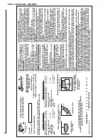
1. Using framing lumber equal to ceiling joist
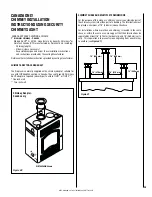
size, frame ceiling opening as shown in
Figure 27
and
Table 4
.
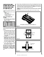
5. The first chimney section through the joist area into attic is to be approximately two (2) feet.
If the pipe sections in the attic are not enclosed, an insulation shield (SPIS) must be installed.
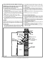
Lower the insulation shield (SPIS) over the SP pipe until the SPIS flange is resting on the joist.
Secure the SPIS in place by nailing the flange to the joist. See
Figure 29
. If the section within
the attic area is to be chase enclosed, the SPIS is not required.
WARNING: Do not place any type of insulation in the required clearance spaces surrounding
the chimney.
6. Continue the chimney to the roof. See “Flashing Installation”and “Termination” sections.
B
A
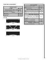
Framing lumber of equal size to the joist should be used.
Figure 28
FEMALE END
MALE END
BUTTON LOCK
ATTACH FOR LOCK
Figure 29
INSULATION SHIELD
(CAT. NO. SPIS)
NAIL
FIRESTOP
(CAT. NO. SPFS)
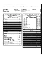
Chimney Flue Diameter
7”
A
13-7/16”
B
13-7/16”
Table 4
If the area above the ceiling is an attic, go
to step 5.
2. Install SNAP-PAK chimney sections start-
ing at the top of the appliance. Leave the
first section loose until the installation is
complete to allow the chimney to be ro-
tated, easing the installation of any offsets
if they are used. Secure subsequent sec-
tions by pushing together until stop-locked
(see
Figure 28
).
3.
If IHP Elbows are to be used because the
chimney is to be offset, refer to “Instal-
lation of Elbows” section.
Directly above
the Center of the flue in the ceiling support,
mark the ceiling. A plumb bob is normally
used to find the center. Cut an opening in
the ceiling using
Figure 28
and
Table 4
.
4. At each ceiling penetration, a firestop
(SPFS) is required. Insert the SPFS into the
joist area prepared in
Figure 27
.
NOTE: When the chimney extends between
floors-which can be occupied-the chimney
must be enclosed to prevent contact. As
previously noted, 2” minimum clearance
to combustibles is to be maintained at all
times.
Figure 27


