Questions? Call or Text +1-801-658-0015 •
39
The Micro Welder Experts
• Click the Send button.
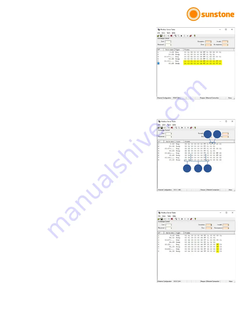
• The request you just entered will be displayed in the
main window of the Modbus Server Tester app, along
with a response. Both the request and response should
match, as highlighted in Figure 39.1. The 0xFF signi-
fies that a “ON” true was sent Notice that the CDDP-
A’s Home screen will indicate that the Pulse 1 Power
Comparator is enabled, as shown in Figure 39.2.
If you write to the same output address but change the output
value to “OFF” and hit “Send” you will notice that the Pulse
1 Power Comparator on the welder is now disabled. Further,
the output windows will display a 0x00 instead of 0xFF in the
request and response, signifying that a “OFF” false was sent.
READING THE OUTPUT WINDOW: REQUESTS AND
RESPONSES
Each time you send a request the first two columns of data in
the Frame section will increment (A), as highlighted in Figure
39.2.
The third through seventh columns in the Frame section is part
of the header that is sent/received (B) as shown in Figure 39.2.
The column after the columns with “FF” data, or the eight col-
umn, is the Function code (C) as shown in Figure 39.2.
The next column (D) is the byte count, as shown in Figure 39.2.
The next column (E) shows the 2 bytes received when reading
the coil.
When writing to a single coil output, the request and response
will match with either 0xFF ON or 0x00 OFF when writing to a
single coil. See highlighted section in Figure 39.3.
READING THE INPUT REGISTER
Follow these steps to read from the Input Register Function
Code.
• Send a new frame by clicking on the Send Frame icon in
the upper toolbar.
• In the Send New Frame window, select 04 Read Input
Registers.
Figure 39.1.
Figure 39.2.
Figure 39.3.
A
B
C
D
E


