background image

12

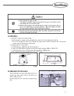
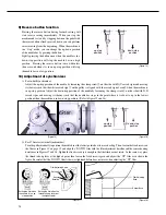
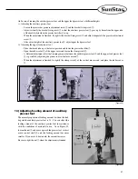
[Figure 7]

[Figure 8]

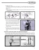
6) Installation of belt cover

Fix the belt cover 

A

”①

to the machine

s body using 3 fixing screws

.

You can assemble it more easily if you slightly incline the machine.

When the assembly of the belt cover 

A

is finished, insert the front side of the belt cover 

C

”③

into the groove of belt

cover 

A

”①

and fix the back side with the fixing screw

.

Attach the belt cover 

B

”④

to the table.

Please make sure that the belt do not intervene with the inside of the belt cover 

B

”④

.

7) Installation of synchronizer 

(for automatic trimming type)

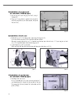
Installing on the servo motor 

In case of installing the servo motor (in-built synchronizer), a

synchronizer sensor is attached to the backside of the arm.

The appropriate clearance between the synchronizer and the

pulley is 1.2mm. 

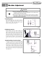
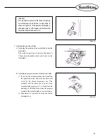
[Figure 9]

[Figure 6]

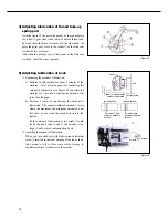
5) Installation of program unit 

(for automatic trimming type)

Fix the bracket

onto the program unit

, using 4

fixing nuts

Then, use 2 fixing bolts

to tightly fix the bracket

,

where the program unit 

has been adjusted, along with

the back cover. 

Содержание KM-640BL

Страница 1: ...k stitch machine with automatic thread trimmer with large hook KM 640BL Long arm type one needle upper lower feed lock stitch machine with large hook 1 For proper use of the machine thoroughly read this manual before use 2 Keep this manual in a safe place for future reference in case the machine breaks down M MM ME E 0 05 50 06 62 29 9 ...

Страница 2: ... functions high performance powerful operation enhanced durability and more sophisticated design to meet a number of user s needs 2 Please read this user s manual thoroughly before using the machine Make sure to properly use the machine to enjoy its full performance 3 The specifications of the machine are subject to change aimed to enhance product performance without prior notice 4 This product is...

Страница 3: ...ng of needle and hook 15 4 Adjusting lubrication of thread take up spring part 16 5 Adjusting lubrication of hook 16 6 Winding and adjusting lower thread 17 7 Inserting and removing lower thread and adjusting tension 17 8 Routing upper thread 18 9 Adjusting upper thread 18 10 Adjusting presser foot pressure 19 11 Adjusting stitch length 19 12 Adjusting feed dog height and inclination 20 13 Adjusti...

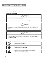
Страница 4: ...all be observed strictly Otherwise the user will be killed or suffer severe physical injuries Instructions here must be observed or the user could suffer fatal or severe physical injuries Instructions here should be observed or the user could face physical injuries or mechanical damages Danger The meaning of symbols This symbol means a must not Warning Caution 4 This symbol means that an electric ...

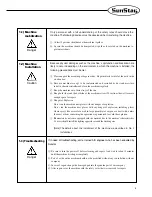
Страница 5: ...function and breakdown are likely to occur depending on the environment in which the machine is installed the following preconditions must be met ⓐ Please unpack the machine package in order Be particularly careful of the nails in the wooden box ⓑ Because machines are apt to be contaminated and corroded by dust and moisture install a climate controller and clean the machines regularly ⓒ Keep the m...

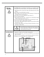
Страница 6: ... when threading the needle or before checking after sewing ⓗ Do not switch on the power supply with the foot on the pedal ⓘ Do not run the machine when the cooling fan is clogged Be sure to clean the air filter in the control box once a week ⓙ If possible keep the machine away from strong electromagnetic fields like areas around a high frequency welding machine 1 4 Machine Operation Caution Cautio...

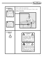
Страница 7: ...Be sure to wait at least 360 seconds before opening this cover after turn off main switch and unplug a power cord 고압 전류에 의해 감전될 수 있으므로 커버를 열 때는 전원을 내리고 전원 플러그를 뽑고 나서 360초간 기다린 후 여십시오 CAUTION 경 고 Do not operate without finger guard and safety devices Before threading changing bobbin and needle cleaning etc switch off main switch 손가락 보호대와 안전장치 없이 작동하지 마십시오 실 보빈 바늘교환시나 청소전에는 반드시 주전원의 스위치를 꺼 주십시오 CAUT...

Страница 8: ...ngth Needle Thread take up stroke Needle bar stroke Presser foot stroke Manual Auto Hook Usage Model Name Item KM 640BL 7 KM 640BL Max 2 000 SPM Max 2 500 SPM Max 9mm DP 17 22 DB 1 22 73mm 38mm 2 5 5mm 7mm 16mm Vertical rotation hook Heavy materials 2 Servo motor MODEL SC55 1A SC55 2A SC55 3A VOLT 1 Phase 110V 1 Phase 220V 3 Phase 220V WATT 550W 550W 550W HERTZ 50 60 Hz 50 60 Hz 50 60 Hz 3 470 mot...

Страница 9: ...lable in two types SEDG 1B for edge sensing type and SEDG 2B for thickness sensing type An essential device when one person is operating multiple sewing machines Has different pedals for acceleration thread trimming presser foot and ascending pedal Types consist of SPDL 1 and EDPL 1 for fixed speed and SPDL 2 and EDPL 2 for variable speed SPF 7 A solenoid operating structure where the presser foot...

Страница 10: ...Installation Warning Installation of the machine should be performed by a trained engineer Any electrical wiring must be performed by a qualified technician or agent The machine weighs over 43kg At least 2 persons should carry out the installing work Plug in after the installation is complete If the operator mistakenly steps down on the pedal with the pug in the machine will start automatically an...

Страница 11: ...nging lubricant is 1 time in two weeks oil pump magnet Caution Plug in only after oil supply is finished If the operator mistakenly steps on the pedal with the plug in the machine will start automatically and can cause severe injuries When handling lubricants wear protective glasses or gloves to avoid contact with your eyes or skin Inflammation may be caused otherwise Never drink lubricants since ...

Страница 12: ... that the belt do not intervene with the inside of the belt cover B 7 Installation of synchronizer for automatic trimming type Installing on the servo motor In case of installing the servo motor in built synchronizer a synchronizer sensor is attached to the backside of the arm The appropriate clearance between the synchronizer and the pulley is 1 2mm Figure 9 Figure 6 5 Installation of program uni...

Страница 13: ... a long time ago open the face plate and spray oil using lubricator to the thread take up connecting part and fraction parts such as needle bar and pushing bar When you do test running of machines run intermittently the machines for about 10 minutes at rotation of 1 500 spm For the first 4 to 5 days run the machine less than 1 500 spm per minute and later run the machine at the normal rotation so ...

Страница 14: ...m when the machine is in up stop position Adjust the down stop position of the needle by loosening the clamp screw on the side with N D carved signs and moving it sideways such that the needle bar stops in the point where it is about to up in the lowest position when the machine is in down stop position Refer to figure 15 and 16 For 470 motor external synchronizer Turn the pulley manually to posit...

Страница 15: ...and hook As in Figure 21 align the lower side of the needle bushing with the fixed hook position carved line marked in the needle bar Then loosen three hook fixing bolts When the hook edge is aligned with the center of needle turn the loosened hook so that the clearance between the needle groove inside carved in the lateral side of the needle and the hook edge becomes 0 05 0 1mm Later tight again ...

Страница 16: ...e for 5 seconds to confirm the amount of oil sprayed to the paper b Perform 3 times of confirming the amount of lubrication The adequate adjusted amount is a state where the maximum and minimum amounts do not fall short of or exceed the amount shown in the picture If the amount of lubrication is too small it could invite the hook seizure and if the amount is too large it could cause a contaminatio...

Страница 17: ...ning and it decreases when you turn counterclockwise Figure 25 7 Inserting and removing lower thread and adjusting tension Insert the bobbin into the bobbin case Later insert the thread into the thread groove and place it under the spring of thread adjusting plate The tension of the lower thread becomes larger when you turn clockwise the tension adjustment screw and becomes smaller when you turn i...

Страница 18: ...e thread take up tension As in Figure 27 insert the driver into the groove of the thread tension control assembly Turn clockwise to make the spring tension stronger and counter clockwise to make it weaker Upper thread tension is weak while the lower thread tension is weak upper thread tension is strong while the lower thread tension is weak good swing Caution Turn off the power switch when routing...

Страница 19: ... 11 Adjusting stitch length As shown in Figure 29 the number marked in the stitch control dial means the stitch width in mm Adjust it in sideways and fix it to your desired number of stitch width Figure 28 Figure 29 stronger weaker weaker stronger Caution After disassembling and adjusting a safety device always place it back to the original position and check whether it functions as intended Use b...

Страница 20: ...h the material type there are some cases in which run the auxiliary presser foot and the upper feed presser foot at the same pace or sometimes at different paces In these cases please adjust the height as follows In case of running vertically the auxiliary presser foot and the upper feed presser foot at the same height a The vertical running range of the auxiliary presser foot and the upper feed p...

Страница 21: ...ter Open the rubber cover of the upper cover and loosen the clamp screw A different adjustment of vertical running amount between the auxiliary presser foot and the upper feed presser foot is possible by adjusting the presser foot vertical move crank When the adjustment is finished fix tightly the clamp screw of the vertical move crank and place the rubber cover Figure 32 14 Adjusting feeding amou...

Страница 22: ...thread trimmer of this machine is as follows in Figure 35 Caution This sewing machine is run by the thread trimming driving method which uses the cam attached to the lower shaft as driving force Thus if you rotate the machine with the thread trimming solenoid is in operation in time of the machine adjustment the moving knife collides with the needle causing harms on the both parts So when you run ...

Страница 23: ...cautious in adjusting the right position Adjusting the trimmer driving part a The standard assembly position is shown in Figure 37 b Fix the thread trimming following crank to the trimming shaft as shown in the figure c Fix the stopper lever to the bed so that the lever can smoothly rotate in a range where the gap of the trimming shaft does not occur stopper lever Adjusting the thread trimmer sole...

Страница 24: ...oid link fixing screw solenoid link pin solenoid base solenoid base fixing screw thread release cable fixing nut thread trimming following crank solenoid arm Figure 40 Adjusting the thread trimming cam a Like in Figure 40 align the second timing carved line Green of the pulley with the arm s carved line green carve line carve line Figure 41 b Under the thread trimming solenoid is in operation rota...

Страница 25: ...xed blade The standard position of the movable knife is 7 5mm from the needle center and 5 mm for the fixed blade Figure 44 b Adjusting the progress amount of the movable knife If you run the machine putting the solenoid in the operation mode the movable knife will rotate by the thread trimming cam The standard will be where the cut part of the movable knife progresses 1 5 to 2mm from the end edge...

Страница 26: ... To exchange the movable knife turn the pulley with hands such that the needle can be located in the highest position and separate the needle plate And loosen the two fixing bolts of movable knife shown in Figure 47 and break it up In case of assembling the exchanged part please perform this in a reverse manner Figure 47 19 Exchanging fixed blade When you exchange the fixed blade loosen first the ...

Страница 27: ...g amount of upper thread Adjust the remaining amount of upper thread is adjustable with the auxiliary thread tension adjusting nut The remaining thread becomes shorter when you turn it right and the thread becomes longer if you turn left Refer to Figure 51 Figure 51 Caution If the gap of the control dish is too narrow it invites the shortening of the upper thread causing a possible thread missing ...

Страница 28: ...sition Too tight upper thread tension Too tight lower thread tension Loose upper thread Upper and lower thread tensions are bad Thread take up spring tension is inadequate The gap between the opener and hook is inadequate Needle is inserted into wrong position Needle is bent Wrong direction The timing between the needle and hook is bad The length of the remaining upper thread is too short After tr...

Страница 29: ...29 5 Table Drawing 1 KM 640BL ...

Страница 30: ...30 2 KM 640BL 7 ...

Отзывы: