24
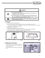
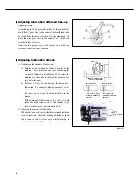
b) Adjusting the thread trimming solenoid
①
First, loosen the solenoid link pin fixing screw. Later, fix the solenoid base clamp screw where the clutch lever
moves smoothly. Then, attach the slide arm to the right side. Fix the thread trimming solenoid link pin fixing
screw where the solenoid stopper is attached to the solenoid.
②
If you run the solenoid under this circumstance, a gap of 0.5mm occurs between the thread trimming following
crank and the slide arm as shown in Figure 39. This state is the standard.
[Figure 39]
solenoid link fixing screw
solenoid link pin
solenoid base
solenoid base
fixing screw
thread release cable fixing nut
thread trimming following crank
solenoid arm
[Figure 40]
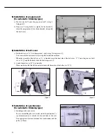
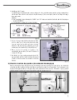
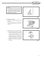
Adjusting the thread trimming cam
a) Like in Figure 40, align the second timing carved
line (Green) of the pulley with the arm
’
s carved
line.
green
carve
line
carve
line
[Figure 41]
b) Under the thread trimming solenoid is in operation,
rotate the trimming cam clockwise and fix the cam
when it connected with the roller. (Refer to Figure
41)
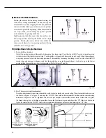
c) When the thread cam following crank returned by
stopping the operation of the thread trimming
solenoid, the edge end between the cam and the
roller should be from 0.5 to 1.0mm. It is the
standard. (Refer to Figure 40)
0.5~1mm
Содержание KM-640BL
Страница 29: ...29 5 Table Drawing 1 KM 640BL ...
Страница 30: ...30 2 KM 640BL 7 ...


