WARNING!
B
screw
D
E
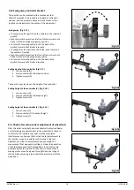
Fig. 5.10
Fig. 5.11
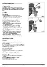
Fig. 5.12
Fig. 5.13
(B) (Fig.5.1
2
).
247556 Rev. A
17
Q700-UP M
S
et foot plate height and angle
S
et foot plate angle:
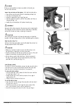
• After adjustment and with the seat in its normal drive position:
Ensure there Is a gap of at least 2" (
51
mm.), between the
floor
and the footplate at all times when maneuvering the
footplate
up or down.
• Perform this test with the user sitting in the chair loading the
leg
rest.
Using the chair with the leg rest set too low might result in
personal injury or damage to the wheelchair and its surroundings.
• Remove bolt (D) with an Allen key (Fig.5.
13
).
• Move spacer (E) from inside of footrest to the outer side.
• Reinsert bolt and tighten securely.
• Repeat for the other side.
•
Use 5mm Allen key to remove the two bolts (A) on the outside
edge of the PCM legrest. Repeat for the other side
, (Fig.5.
10 and 5.11
).
•
Slide the footplate down to the desired position. The adjustment
holes on this side tube are spaced 20mm (0.78in) from each other
with a maximum of 80mm (3.15in) of additional length.
• Use 5mm Allen key to tighten the bolts on both sides.
The power center mount footrest allows angle adjustment from
90° to 180° level to ground and a
7.5" (190 mm)
powered length
extension.
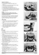
The left and right footplate can be adjusted by an angle of
+/-5.0° and has a mechanical height range adjustment of
11.8"
to 16.7"
(
301
mm to
424
mm) measured from the footplate to
the seatpan.
•
Flip up the footplate so that you can reach the angle setting
•
on the angle required.
Use a 4mm Allen key to adjust the bolt in or out
d
epending
S
et foot plate
height:
A
S
et foot plate width:


