8
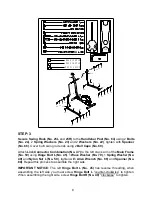
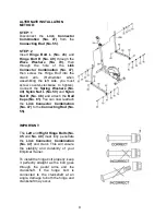
STEP: 3
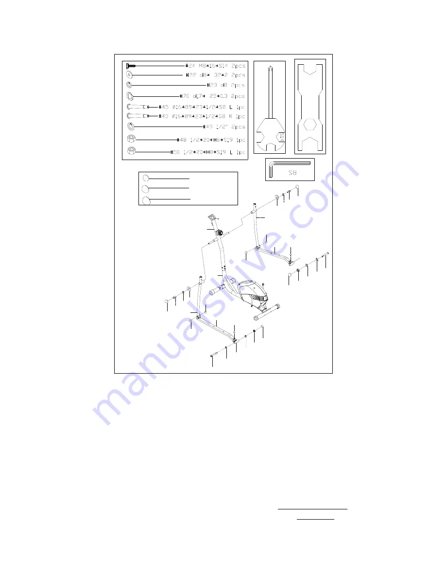
Secure Swing Rods (No. 25L
and
25R)
to the
Handlebar Post (No. 64)
using 2
Bolts
(No. 24)
, 2
Spring Washers (No. 23)
and 2
Washers (No. 22)
, tighten with
Spanner
(No. 68)
. Cover both swing rod ends using 2
Ball Caps (No. 60)
.
Attach
Link Connector Combination (No. 47)
to the left crank arm of the
Main Frame
(No. 59)
using
Hinge Bolt L (No. 45)
, 1
Wave Washer (No. 70)
, 1
Spring Washer (No.
49)
and
Nylon Nut L (No. 50)
, tighten with
Allen Wrench (No. 66)
and
Spanner (No.
69)
. Repeat this process to assemble the right side.
IMPORTANT NOTICE:
The left
Hinge Bolt L (No. 45)
has reverse threading, when
assembling the left side you must screw
Hinge Bolt L
“counter-clockwise” to tighten.
When assembling the right side, screw
Hinge Bolt R (No. 40)
“clockwise” to tighten.
45
49
50
61
¦ µ
24
23
22
25R
60
60
60
61
48
49
40
24
22
23
60
S19
#60 S13 6PCS
#62 S16 2PCS
#61 S18 2PCS
25L
55
64
59
47
47
60
62
55
60
62
¦ µ
70
70
Содержание SF-E3416
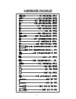
Страница 6: ...5 HARDWARE PACKAGE ...


