


29
6
Communication
6.1
Communication Terminal
The RS485 communication terminal is located at the bottom of the inverter. User
can connect a communication module or cable to the terminal.
Module/Cable Function
SolarInfo Wi-Fi
module
Communication between the inverter and the smart phone can
be established via SolarInfo Wi-Fi. Use SolarInfo Home APP to set
the country and protection parameters according to the
permissible range of the utility grid. Refer to the User Manual of
Wi-Fi for details.
eShow
(LCD display )
Perform the LCD operation to set the country and protection
parameters according to the permissible range of the utility grid.
Refer to
eShow User Manual
for details.
ZE100
ZE100 mainly provides the zero export function, LCD display and
so on. Refer to the
ZE100 User Manual
or
ZE100 Quick Installation
Guide
for details.
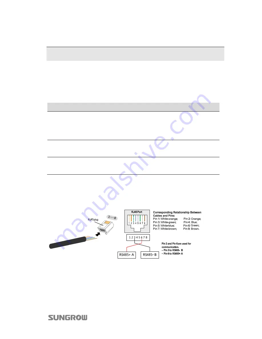
If a RS485 cable is connected to the terminal, use a Ethernet crimper to crimp wires
and connect the wires to the RJ45 plug according to TIA/EIA 568B standard.
Pin 3 (white-green wire as RS485 B) and pin 6 (green wire as RS485 A) are used for
communication. Please do not use pins 1, 2, 4 and 5. Refer to the figure below.
This chapter mainly describes the communication between the inverter and the
smartphone/router. Refer to "
10 FAQ for SolarInfo Wi-Fi Installation and
Configuration
" for any problems.


