background image

insulation  shall  have  a  maximum  operating  tempera-
ture of 220

°

F or higher. The wall thickness of the pipe 

insulation should be not less than 

1

/

2

”.  A 1” wall thick-

ness is required for exposed piping in all areas prone to 
annual hard freeze conditions.  When it comes to pipe 
insulation the rule is simple: thicker is better. 

To  the  extent  possible,  slide  the  insulation  material 
over  the  pipe  without  cutting  or  taping.  All  butt  joints 
must be sealed with contact adhesive. The use of rigid 
polyethylene pipe insulation is prohibited. The temper-
atures  generated  by  your  collector  in  the  summer 
months  or  under  stagnation  conditions  can  melt  this 
type of material. 

Any above ground exterior pipe insulation is subject to 
UV  degradation  and  must  be  jacketed,  wrapped  with 
aluminum  foil  tape,  or  painted  with  two  coats  of  high 
quality water-based acrylic resin coating as supplied by 
the insulation manufacturer. 

4.6 Control System 

4.6.1 Differential Controller 

The differential controller must be installed in an acces-
sible  location  so  that  the  user  interface,  typically  an 
LCD  screen,  can  be  seen.  Switches  on  the  controller 
must be labeled and accessible. Always follow the con-
troller manufacturers wiring instructions when installing 
differential  controllers.  Control  system  inputs;  such  as 
signals  from  the  temperature  sensors  or  flow  meters 
shall  be  connected  to  the  appropriate  low  voltage  ter-
minals. Controller output to the pumps will be medium 
voltage,  110  VAC  or  220  VAC.  Medium  voltage  power 
to  the  pump  may  be  supplied  by  a  line  cord  from  the 
pump to an outlet in the controller or hard wired from 
the  controller  medium  voltage  terminals  to  the  pump. 
Wiring  must  comply  with  standard  electrical  practice 
and  all  applicable  electrical  codes  for  the  jurisdiction 
having  authority,  this  may  require  the  use  of  conduit 
for medium voltage wiring. 

The  differential  controller  must  have  a  provision  to 
manually  turn  the  pump  on  and  off  (manual  override) 
so that the pump operation can be checked at any time 
and the pump can be manually stopped if required for 
maintenance or troubleshooting purposes. 

Set  the  maximum  tank  temperature  to  the  desired 
maximum temperature, this temperature must be low-
er than the rated maximum temperature of the tank an 
associated components. When the solar loop heats the 
tank to the temperature, the pump will shut off  

preventing further heat gains to the solar tank.


4.6.2 Collector Sensor Placement 

The  collector sensor shall be located  on the  solar loop 
return line as close to the collector as possible. Sensors 
are typically accurate to 

±

1

/

2

°

F if properly installed and 

weatherized.  The  collector  probe  sensor  shall  be  at-
tached  to  the  SunEarth  collector  header  pipe  either 
with  a  stainless  steel  hose  clamp  or  by  inserting  the 
probe  sensor  into  a  thermal    well   in  contact  with  the 
fluid near the outlet header pipe. 

It  is  recommended  that  the  connection  between  the 
silicon  sensor  lead  and  low  voltage  sensor  wiring  be 
made inside the attic, a NEMA 4X junction box or some 
other indoor space. When using wire nuts to make the 
connection,  the  crimped  brass  cap  on  the  end  of  the 
sensor should be removed and the wire stripped before 
inserting into  the  wire  nut  for  connection.  Where  con-
nections from the sensor lead to the low voltage wiring 
is  made  at  an  exposed  location  the  connection  should 
be  crimped and insulated with heat  shrink or  soldered 
and insulated with heat shrink. Wire nuts or screw con-
nectors should not be used in exposed locations due to 
the  likelihood  of  corrosion  which  will  result  in  a  com-
promised  electrical  connection.  Thoroughly  wrap  and 
weatherize the insulation with electrician’s tape or insu-
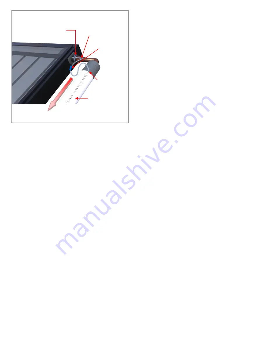
lation  tape  as  provided  by  the  manufacturer.  See  Fig-
ure 12 for collector sensor installation detail. 

If  an  electrical  potential  exists  between  the  roof  and 
ground, this may induce current in the collector sensor 
wire. This current will result in a false signal being re-
ceived  by  the  controller  and  hence  incorrect  tempera-
ture measurements. To prevent this current the collec-
tors absorber plate and piping should be independently 
earth  grounded.  This  will  provide  a  separate  path  to 
ground from the roof which does not interfere with the 
sensor readings. 

Grounding  can  be  achieved  by  running  a  separate 
ground wire to the collectors or ensuring that the pipe 
in  the  solar  loop  is  grounded  and  that  there  are  no 
electrical  discontinuities  between  the  grounding  point 
and the collectors absorber. Grounding of the collector 
&  roof  piping  is  especially  important  in  locations  that 
often experience electrical storms and electrical atmos-
pheric activity.  

4.6.3 Low Voltage Wiring 

The  low  voltage  wiring  used  in  to  connect  the  sensor 
lead to the controller shall be a minimum 18 AWG. The 

COLLECTOR SENSOR 

Fig.12 

SILICON SENSOR LEAD MAY 
BE IN CONTACT WITH PIPE 

SENSOR CLAMPED TO HEADER PIPE 
& COVERED WITH INSULATION 

CRIMP OR SOLDER 
CONNECTION 

SENSOR WIRE 

MUST 

NOT 

BE PLACE IN 

DIRECT CONTACT 
WITH PIPE 

PROTECTIVE INSULATION 
JACKET OR APPROVED 
COATING 

RETURN LINE 

Содержание CASCADE 2

Страница 1: ...SRCC OG SRCC OG 300 Certified Solar Water Heating System 300 Certified Solar Water Heating System Installation Operation and Maintenance Manual Installation Operation and Maintenance Manual ...

Страница 2: ...stem certification is granted to SunEarth by the SRCC It may not be used for any commercial purpose without prior written consent of SunEarth SunEarth must approve any deviation from the mate rials and methods described in this manual in writing The Cascade 2 Drainback solar water heating systems can be protected against freeze damage to temperatures as low as 50ºF 46ºC This system should not be i...

Страница 3: ... Isolation Procedures 14 8 Vacation procedures 14 9 Maintenance and Troubleshooting 14 10 Cascade 2 System Component Parts 15 11 Estimated Component Life 16 12 System Operating Parameters 16 Appendix A Approved Primary Components 18 Appendix C System and Component Labels 22 Appendix F SunEarth Collector Warranty Statement 24 Appendix G SRCC OG 300 Certified System Model Numbers 26 Appendix H Suppl...

Страница 4: ...ng to prevent con tact with HOT water NOTICE Mixing valves should be installed to reduce the point of use water temperature by mixing hot and col wa ter in branch water lines Contact a licensed installer or the local plumbing authority for further information The temperature of the water in the water heater can be regulat ed by setting the temperature dial of the adjustable surface mounted thermos...

Страница 5: ...cian or the local utility SAFETY PRECAUTIONS Have the installer show you the location of the circuit breaker and how to shut it off if necessary Turn off the circuit breaker if the water heater has been subjected to over heating fire flood or physical damage or if the ECO fails to shut off Read this manual entirely before in stalling or operating the water heating system Use this appliance only fo...

Страница 6: ...e fluid water in the collector array and solar loop piping drains back by gravity into the drainback storage reservoir when the pump stops circulating Air replaces water in the col lector array and solar loop piping to prevent it from freezing when the pump is off This manual is intended as a basic solar water heating primer Our goal is to familiarize you with the proper installation operation and...

Страница 7: ...r of any existing roof damage or necessary repairs 3 5 Structural Considerations The collectors must be located in a structurally sounds area of the roof Penetrations into structural members must not compromise the structural properties of the member ENSURE THAT ALL STRUCTURAL MEMBER PENE TRATIONS COMPLY WITH APPLICABLE CODES The collector mounting method must be capable of maintaining the require...

Страница 8: ...nEarth Solar Collector s 2 3 4 Temperature Sensor 5 6 7 8 22 Ball Valve 11 24 35 36 Combination Valve 9 Pressure Relief Valve 10 Drain Back Tank 12 13 Pump 14 Heat Exchanger 17 Differential Temperature Controller 18 Heating Element Tank Thermostat 19 20 Temperature and Pressure Relief Valve 21 Mixing Valve 23 Water Heater 25 Solar Tank 22 35 ROOF JACKS 36 ...

Страница 9: ...l Valve 11 24 35 36 Combina tion Valve 9 Pressure Relief Valve 10 Drain Back Tank 12 13 Pump 14 Heat Exchanger 17 Differential Temper ature Controller 18 Heating Element Tank Thermostat 19 20 Temperature and Pressure Relief Valve 21 Mixing Valve 23 Water Heater 25 Solar Tank 20 48 min T1 21 9 17 4 3 10 11 12 13 14 T3 PIPE INSULATION T2 22 24 23 25 35 ROOF JACKS 36 ...

Страница 10: ...25 1 SunEarth Solar Col lector s 2 3 4 Temperature Sensor 5 6 7 8 22 Ball Valve 11 24 35 36 Combina tion Valve 9 Pressure Relief Valve 10 Drain Back Tank 12 13 Pump 14 Heat Exchanger 17 Differential Temper ature Controller 18 Heating Element Tank Thermostat 19 20 Temperature and Pressure Relief Valve 21 Mixing Valve 23 Water Heater 25 Solar Tank 35 ROOF JACKS 36 ...

Страница 11: ...slope is 1 4 vertical drop per foot of horizontal piping run 2 minimum slope Use the steepest slope possible on the return line piping to the drainback reservoir Water will drain down both the return tubes directly to the drainback reservoir and the supply tubes by spinning the pump impeller in the re verse direction The collector should be mounted as close to the stor age tank as possible to mini...

Страница 12: ...tions The PEX tubing shall not be exposed to sunlight Water must be used as the heat transfer fluid The system shall be non pressurized capped at at mospheric on the day of installation or shall be vented to atmosphere A length of uninsulated copper tube no less than nominal diameter shall be used at the hot outlet and cold inlet of the solar collector s for a distance of no less than three feet 3...

Страница 13: ...e System out lined below All vertical piping between the storage tank and the collector shall be supported at each story or at maxi mum intervals of ten feet 10 Horizontal runs shall be sloped to drain minimum 2 slope and supported every five feet 5 to prevent sagging Roof runs shall be secured and supported providing at least 1 1 2 inches clearance from roof Pipe supports shall be con structed fr...

Страница 14: ...ector Sensor Placement The collector sensor shall be located on the solar loop return line as close to the collector as possible Sensors are typically accurate to 1 2 F if properly installed and weatherized The collector probe sensor shall be at tached to the SunEarth collector header pipe either with a stainless steel hose clamp or by inserting the probe sensor into a thermal well in contact with...

Страница 15: ...lumbing is required to provide for the isolation of the solar storage tank from the city cold water supply line by means of an isolating ball valve The differential temperature controller shall have a screen readout to show temperatures of the collector and storage tank Otherwise line thermometers shall be installed in the collector supply and return lines to allow for a simple diagnostic check of...

Страница 16: ... concrete slab in order to prevent moisture damage to the base of the tank and reduce the heat loss to the floor The tank should be raised off the floor on a pad 4 10 Choosing and Installing the Drainback Res ervoir SunEarth CopperStorTM copper drainback tanks are available in 2 5 5 7 5 and 10 gallon capacities Stain less steel drainback tanks are available in 10 15 and 20 gallons Small glass line...

Страница 17: ...illing the System Once the components have been plumbed it is time to fill the solar storage and collector loop with water as follows 4 14 1 STEP 1 Flush and Fill the potable loop with water Close potable flushing combination valves COMPONENTS 24 36 Fill the solar tank with wa ter and check that there are no leaks on the potable side of the system Do this by opening the cold water isolation ball v...

Страница 18: ...lso have been visual ly inspected for leaks and the solar loop piping has been cleaned and charged Having successfully com pleted these tasks it is time to set your system to run automatically Set the SunEarth control to the ON position Listen until you can hear water flowing through the solar loop return piping from the collector Place your ear next to the pump and listen for signs of cavitation ...

Страница 19: ...ons in excess of sixty days Remember to reset the SunEarth control to the AUTO position upon your return and check the system for proper operation and draining by monitoring the water levels with the pump on and off 9 MAINTENANCE AND TROUBLESHOOTING The following simple procedures are intended to opti mize the performance of your Torrent Drainback solar water heating system and also to extend the ...

Страница 20: ...e pump is running and the controller displays questiona ble temperatures at the collector or tank i e 180ºF tank and 45ºF collector check both sensors using a resistance meter to see if they are correctly calibrated If you find a defective sensor replace it immediately 9 10 Auxiliary Electric Element not Operating If the weather is poor and the auxiliary heating ele ment will not fire the bright r...

Страница 21: ...d by the plumbing code on water heaters Will automatically release and dump water at either 150 PSI of pressure or 210 F in temperature 21 Mixing Valve Automatically blends hot water from the solar storage tank with incoming city cold wa ter to an acceptable set point A mixing valve must be installed on every Torrent Drainback solar water heat ing system The mixing valve may include and integral c...

Страница 22: ...he system is not circulating pump stopped should such that the drainback tank not less than 75 full When the system is circulating pump running the water level in the drainback tank should be not less than 25 full The drainback tank should never be pumped dry in normal operation as this may result in damage to the circulator pump ...

Страница 23: ...pire Chrome EC 21 EC 24 EC 32 EC 40 EC 24 0 75 EC 32 0 75 EC 40 0 75 EC 24 1 5 EC 32 1 5 EC 40 1 5 SunEarth SunBelt SB 24 0 75 SB 32 0 75 SB 40 0 75 SunEarth Imperial Chrome IC 32 IC 40 SunEarth Imperial Selective IS 32 IS 40 SunEarth ThermoRay TRB 32 TRB 40 Make Series SunEarth SolarStrut RexRack Flush Mount Kit Universal Tilt Kit Landscape Rack Make Series Model Numbers SunEarth SunEarth SU80U 1...

Страница 24: ...ervoir Make Series Model Numbers AIC L Line LA14 10 Make Series Model Numbers SunEarth CopperStor DB 2 5 DB 5 DB 7 5 DB 10 SolarH2OT DBT DBT 10 SS DBT 15 SS DBT 20 SS Rheem Energy Miser 81VP6S 81VP15S 81VP10S 81VP20S A O Smith ProMax EJC 6 EJC 10 EJC 20 Or Approved Equal ...

Страница 25: ...e brass or stainless steel construction Maximum working temperature shall be no less than 200 F and maximum working pressure shall be no less than 125 psi Three Way Valves Optional Three Way valves shall be of bronze brass or stainless steel construction Maximum working tem perature shall be no less than 200 F and maximum working pressure shall be no less than 125 psi Boiler Drains A K A Charge Va...

Страница 26: ...rating tem perature of not less than 220o F and maximum working pressure of not less than 125 psi Pipe Insulation Pipe insulation shall have a maximum operating temperature of no less than 220o F All pipes shall be insulated to R2 6 or greater typically this will require a wall thickness of or greater When located in exposed areas pipe insulation shall be protected with a UV resistant coating or j...

Страница 27: ... WHENEVER THE CIRCULATION PUMP SHUTS OFF WHEN PROPERLY INSTALLED AND OPERATED THE SYSTEM IS PROTECTED TO TEMPERATURES AS LOW AS 50 F VALVE NO 8 COLD WATER SUPPLY ISOLATION VALVE THIS VALVE IS NORMALLY OPEN AND ALLOWS POTABLE WATER TO FILL THE SOLAR STORAGE TANK WHEN CLOSED THE SOLAR STORAGE TANK IS ISOLATED FROM THE PRESSURIZED CITY COLD WATER SUPPLY LINE PIPING BOILER DRAIN NO 11 SYSTEM FILL DRAI...

Страница 28: ...EED TO SOLAR TANK ISOLATION VALVE THIS VALVE IS NORMALLY OPEN WHEN CLOSED IN CONJUNCTION WITH VALVE NO 6 IT WILL ISOLATE THE SOLAR STORAGE TANK FROM THE POTABLE WATER SYSTEM VALVE NO 6 HOT OUTLET FROM SOLAR TANK ISOLATION VALVE THIS VALVE IS NORMALLY OPEN WHEN CLOSED IN CONJUNCTION WITH VALVE NO 7 IT WILL ISOLATE THE SOLAR STORAGE TANK FROM THE POTABLE WATER SYSTEM VALVE NO 5 SOLAR TANK BYPASS VAL...

Страница 29: ...APPENDIX F ...

Страница 30: ...APPENDIX F ...

Страница 31: ... 6 1 3 1 1 1 1 0 9 1 3 1 3 2 3 1 6 1 8 1 6 1 5 2 4 1 6 5 2 3 2 1 8 2 3 2 1 7 3 4 2 30004026 30004025 30004024 30004023 30004022 30004021 30004020 30004019 30004018 30004017 30004016 30004015 30004014 30004013 30004012 30004011 30004010 30004009 30004008 30004007 30004006 30004005 30004004 30004003 30004002 30004001 30004000 30003999 30003998 30003997 30003996 30003995 C2 80 120 TLG C2 64 120 TLG C...

Страница 32: ...________ System Information Model Number ___________________________________________ Date Purchased __________________________________________ Collector Serial Number ____________________________________ For Service and Repair Contact ______________________________ Comments ______________________________________________ ________________________________________________________ _____________________...

Страница 33: ...8425 Almeria Avenue Fontana CA 92335 Phone 909 434 3100 Fax 909 434 3101 Email info sunearthinc com www sunearthinc com Revised 3 17 2014 ...

Отзывы: