


Chapter 1
Introduction
1-5
1.2.2
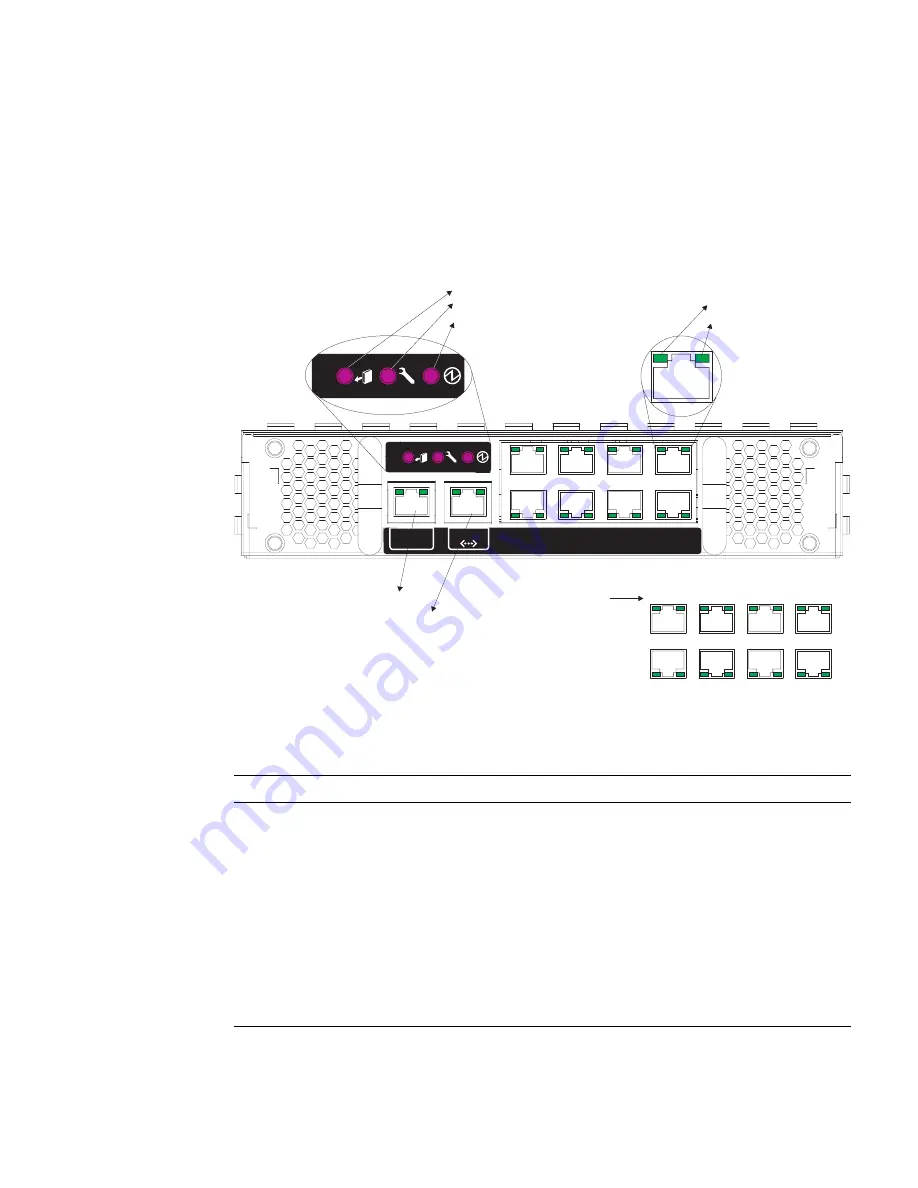
Status LEDs
Switch level indicators are located on the SSC module. The 1000BASE-T up-link ports
and the 10/100BASE-TX management port located on the rear panel of the SSC also
include indicators for both Link and Speed.
FIGURE 1-1
SSC Exterior Panel
TABLE 1-1
Port LEDs
LED
Condition
Status
SSC
Active
On (Green)
The SSC is functioning normally.
Service Required
On (Amber)
The SSC requires service.
Ready to Remove
On (Blue)
The SSC can now be removed.
RJ-45 Ports
Link
On (Green)
Port has established a valid network connection.
Speed
On (Amber)
Link is operating at 1 Gbps.
Off
Link is operating at less than 1 Gbps.
SERIAL
MGT
4
0
5
1
6
2
7
3
NET MGT
Ready to Remove
Service Required
Active
Link
Speed
Serial Mgt. Port
Network Mgt. Port
NETP4
NETP5 NETP6 NETP7
NETP0
NETP1 NETP2 NETP3
Uplink Port
Designations
Содержание Sun Fire B1600 Administration
Страница 4: ......
Страница 17: ...Contents xvii Glossary Glossary 1 Index Index 1 ...
Страница 18: ...xviii Sun Fire B1600 Blade System Chassis Switch Administration Guide June 2003 ...
Страница 38: ...2 6 Sun Fire B1600 Blade System Chassis Switch Administration Guide June 2003 ...
Страница 47: ...Chapter 3 General Management of the Switch 3 9 FIGURE 3 3 Switch Setup System Identity Window ...
Страница 95: ...Chapter 3 General Management of the Switch 3 57 FIGURE 3 19 The Switch Config Broadcast Multicast Window ...
Страница 198: ...3 160 Sun Fire B1600 Blade System Chassis Switch Administration Guide June 2003 ...
Страница 372: ...A 4 Sun Fire B1600 Blade System Chassis Switch Administration Guide June 2003 ...
Страница 392: ...C 6 Sun Fire B1600 Blade System Chassis Switch Administration Guide June 2003 ...
Страница 398: ...Glossary 6 Sun Fire B1600 Blade System Chassis Switch Administration Guide April 2003 ...
Страница 402: ...Index 4 Sun Fire B1600 Blade System Chassis Switch Administration Guide January 2003 ...