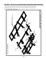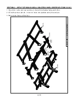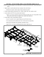
SECTION 2 – SET-UP OF 24’-28’ DISK-CHISEL & COULTER-CHISEL WINGS
2-16
– Insert 7/16 x 3-1/2” bolt in retaining bolt hole. Secure with lock nut.
5. Install walking tandem assembly to bottom of liftarm.
– The left hand wing uses a right hand assembly – 8T4168.
– The right hand wing uses a left hand assembly – 8T4166.
– Slide pivot pin (8T3620) through walking tandem assembly and liftarm.
– Insert 7/16 x 3-1/2” bolt in retaining bolt hole. Secure with lock nut.
6. Hang cylinders in appropriate location. Use pins and roll pins.
– Rod end of cylinder must point towards ground.
– Use 6 x 10” (8T1060) on left hand wing.
– Use 4-1/2 x 10” (8T1045) on right hand wing.
7. Install 8K1100 axle and hub assembly into each walking tandem. Apply good quality anti-seize to
axles before installation. Retain axle into receiver tube with 1/2 x 3-3/4” bolt and locknut.
8. Attach wheels onto hubs with 9/16” wheel bolts (torque required: 170 ft-lbs).
9. 26’ & 28’ Only – Install wing extensions.
– One-shank extension must be placed on rear rank.
– Two-shank extension must be placed on front two ranks.
– Mounting bolts must point toward outside of machine. (Trip assembly interference will occur
if this is not followed.)
10. Hang trip assemblies according to layout provided.
– Use 3/4” u-bolts for 4 x 4 tube with 3/4” lock washers and 3/4” nuts.
– Tighten u-bolts an equal amount on top and bottom. The same amount of threads should ap-
pear on top and bottom of u-bolt.
11. Install Disk Mounting Tubes as shown on page 2-18.
Содержание CoulterChisel CC2815
Страница 6: ...NOTES iv ...
Страница 65: ...2 53 SECTION 2 INSTALLATION OF SHANKS AND COULTER GANGS ...
Страница 126: ...6 26 SECTION 6 PARTS ...
Страница 128: ...6 28 SECTION 6 PARTS ...
Страница 144: ...6 44 SECTION 6 PARTS NOTES ...


