Section 7
MAINTENANCE
34
Use the following instructions as a guide:
1. Disconnect the tubes at the tops of the sight
glass assemblies.
2. Unscrew male connector (for left-side glass), or
the straight thread tube connector (for right-side
glass) from sight glass/orifice blocks.
3. Remove used filter assembly, and replace with
new assembly.
4. Coat/lubricate the o-rings will silicone grease.
5. Reattach the connectors to the sight glass/orifice
blocks.
DIFFERENTIAL
PRESSURE REGULATOR
ADJUSTMENT
Refer to Figure
. The differential pres-
sure regulators are adjusted by loosening the
adjusting screw on the end of the cone-shaped
cover of the pressure regulator. When the jam nut
is loose, turn the adjusting screw clockwise to
increase or counterclockwise to decrease the set-
ting.
The unload pressure regulator should be set at 150
psig (10.3 bar) to control the compressor package
during unload only. The inlet poppet valve control
pressure regulator should be set to control the sys-
tems modulation to the service line desired pres-
sure.
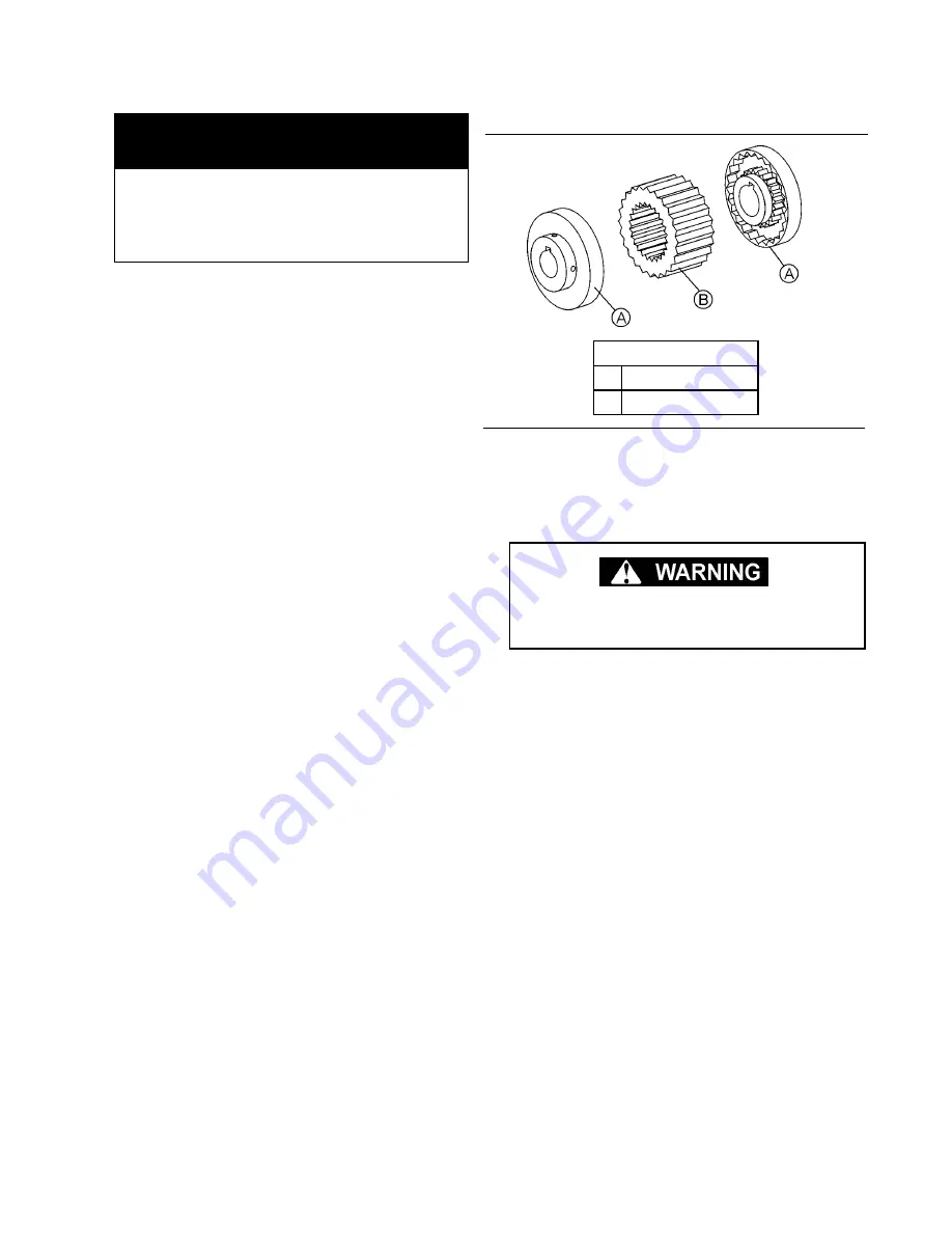
DRIVE COUPLING INSTALLATION AND ALIGN-
MENT
shows layout view of drive sleeve and
coupling hubs.
Figure 7-6 Drive Coupling
What you may need to perform
this maintenance:
Replacement filter assembly no.
02250117-782
Open-ended (size 1/4”) or adjustable
cresent wrench
Units mounted through common housing are
self-aligning. If alignment is suspect, consult
Service Department.
KEY
A
COUPLING HUB
B
DRIVE SLEEVE
Содержание LS20T 1100 CFM
Страница 18: ...Section 2 DESCRIPTION 12 Figure 2 3B Control System Diagram START...
Страница 19: ...Section 2 DESCRIPTION 13 Figure 2 3C Control System Diagram MODULATION...
Страница 20: ...Section 2 DESCRIPTION 14 Figure 2 3D Control System Diagram FULL LOAD...
Страница 21: ...Section 2 DESCRIPTION 15 Figure 2 3E Control System Diagram UNLOAD...
Страница 28: ...Section 3 SPECIFICATIONS 22 Figure 3 2D Identification LS20TS 300 450HP 224 336KW Remote Cooler 02250150 107R01...
Страница 44: ...NOTES 38...
Страница 52: ...Section 9 ILLUSTRATIONS AND PARTS LIST 46 02250142 581R00 9 5 AIR INLET SYSTEM WITH OIL INJECTION VALVE...
Страница 54: ...Section 9 ILLUSTRATIONS AND PARTS LIST 48 02250142 581R00 9 5 AIR INLET SYSTEM WITH OIL INJECTION VALVE...
Страница 64: ...Section 9 ILLUSTRATIONS AND PARTS LIST 58 02250147 357R01 9 9 AIR PIPING SYSTEM 300 450 224 336KW AIR COOLED...
Страница 70: ...Section 9 ILLUSTRATIONS AND PARTS LIST 64 02250147 358R02 9 12 FLUID PIPING SYSTEM 300 450 224 336KW AIR COOLED...
Страница 72: ...Section 9 ILLUSTRATIONS AND PARTS LIST 66 02250147 358R02 9 12 FLUID PIPING SYSTEM 300 450 224 336KW AIR COOLED...
Страница 82: ...Section 9 ILLUSTRATIONS AND PARTS LIST 76 02250138 950R01 9 15 DISCHARGE SYSTEM 300 450HP 224 336KW...
Страница 84: ...Section 9 ILLUSTRATIONS AND PARTS LIST 78 02250138 950R01 9 15 DISCHARGE SYSTEM 300 450HP 224 336KW...
Страница 86: ...Section 9 ILLUSTRATIONS AND PARTS LIST 80 02250138 950R01 9 15 DISCHARGE SYSTEM 300 450HP 224 336KW...
Страница 94: ...Section 9 ILLUSTRATIONS AND PARTS LIST 88 02250152 892R01 9 17 DISCHARGE SYSTEM 500 600HP 373 447KW...
Страница 96: ...Section 9 ILLUSTRATIONS AND PARTS LIST 90 02250152 892R01 9 17 DISCHARGE SYSTEM 500 600HP 373 447KW...
Страница 100: ...Section 9 ILLUSTRATIONS AND PARTS LIST 94 02250155 496R00 9 18 DISCHARGE SYSTEM 500 600HP 373 447KW WITH SWING LID...
Страница 102: ...Section 9 ILLUSTRATIONS AND PARTS LIST 96 02250155 496R00 9 18 DISCHARGE SYSTEM 500 600HP 373 447KW WITH SWING LID...
Страница 104: ...Section 9 ILLUSTRATIONS AND PARTS LIST 98 02250146 367R00 9 19 CONTROL START SYSTEM...
Страница 106: ...Section 9 ILLUSTRATIONS AND PARTS LIST 100 02250146 367R00 9 19 CONTROL START SYSTEM...
Страница 108: ...Section 9 ILLUSTRATIONS AND PARTS LIST 102 02250138 633R00 9 20 CONTROL PANEL...
Страница 110: ...Section 9 ILLUSTRATIONS AND PARTS LIST 104 02250139 119R01 9 21 ENCLOSURE...
Страница 112: ...Section 9 ILLUSTRATIONS AND PARTS LIST 106 02250139 119R01 9 21 ENCLOSURE...
Страница 114: ...Section 9 ILLUSTRATIONS AND PARTS LIST 108 9 22 DECAL GROUP...
Страница 116: ...Section 9 ILLUSTRATIONS AND PARTS LIST 110 9 22 DECAL GROUP...
Страница 118: ...Section 9 ILLUSTRATIONS AND PARTS LIST 112 9 22 DECAL GROUP...
Страница 120: ...Section 9 ILLUSTRATIONS AND PARTS LIST 114 9 23 DECAL LOCATIONS OPEN AIR COOLED...
Страница 122: ...Section 9 ILLUSTRATIONS AND PARTS LIST 116 9 24 DECAL LOCATIONS OPEN WATER COOLED...
Страница 124: ...Section 9 ILLUSTRATIONS AND PARTS LIST 118 9 25 DECAL LOCATIONS REMOTE COOLER...
Страница 126: ...Section 9 ILLUSTRATIONS AND PARTS LIST 120 9 26 DECAL LOCATIONS CONTROL BOX...
Страница 128: ...Section 9 ILLUSTRATIONS AND PARTS LIST 122 9 27 ENCLOSURE DECALS...
Страница 145: ...NOTES 139...


