


SECTION 2
1600C LP USER MANUAL
35
2.12 ENGINE CONTROL MODULE,
FUNCTIONAL DESCRIPTION
Diagnostic Fault Codes are provided to indicate an
electrical or electronic problem has been detected by
the ECM (Engine Control Module). In some cases,
the engine performance can be affected when the
condition causing the code exists. More frequently,
however, the operator cannot detect any difference in
the engine performance.
The Compass Controller indicates a performance
problem has occurred whenever the Engine Warning
Lamp is flashing. The diagnostic code may indicate
the cause of the problem, and should be corrected.
If the Compass Controller does not indicate a
problem with the engine performance but a
diagnostic code is logged by the ECM, the ECM
detected an abnormal condition that did not affect
performance.
If this is the case, unless there are several
occurrences of the code in a very short period of
time, or, the ECM is indicating an Active Code at the
present time, there is most likely nothing wrong with
the system.
The diagnostic FLASH CODE may be retrieved using
this lamp. The lamp is not required for engine
operation, however, it can be useful to determine
Active diagnostic codes. The lamp will illuminate
(ON) at initial ECM power-up to test the lamp
operation (self test).
Count the first sequence of flashes to determine the
first digit. After a two-second pause, count the
second sequence of flashes to determine the second
digit. Any additional flash code diagnostics will follow
(after a pause) and will be displayed in the same
manner.
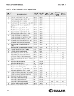
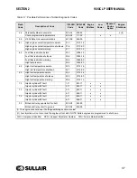
In addition to the flash codes described above, the
Compass Controller should display a brief text
message in the LCD of the master gauge. This
message helps to pinpoint the source of the problem
and aid in troubleshooting the compressor.
Refer to
for possible performance of active
diagnostic codes.
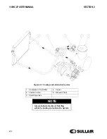
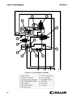
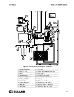
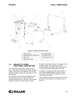
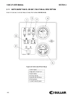
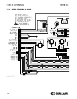
2.13 ELECTRICAL SYSTEM,
FUNCTIONAL DESCRIPTION
Refer to
. The
electrical system is comprised of not only the
necessary equipment required to operate the
compressor, but also a system to shut it down in the
event of a malfunction. The components of the
electrical system are an engine starter (with an
integral solenoid), battery, a breaker protected
alternator with a built-in voltage regulator), a
compressor discharge temperature sensor and
receiver tank temperature switch (both will shut down
the compressor should the compressor temperature
exceed 250
°
F [121
°
C]), an ambient temperature
sensor, and a fuel level sensor. This compressor also
incorporates an engine coolant level sensor. This
device is located in the top of the engine radiator. It
will shut the compressor down or prevent it from
being started if the engine coolant level drops too
low. In addition, there is a starter protection relay
which prevents accidental starter engagement after
the engine is running or whenever there is pressure
in the receiver tank. Also, should fuel supply level
drop near the bottom of the fuel tank, the Compass
Controller will shut down the machine before the
engine runs out of fuel. There are also several
connectors in the main harness that are designed to
receive wiring for factory options such as remote
start, cold weather louvers, engine air stop valve, and
ether start system. The electrical system also
incorporates a lockable battery disconnect to be
utilized for extended periods of non use and during
machine maintenance. In case of emergency, an
emergency stop switch is located just above the
Compass Controller on the canopy of the machine.
NOTE
Only Active diagnostic codes can be read in
this manner. Logged diagnostic codes must
be retrieved with an Electronic Service Tool.
Содержание 02250175-949 R01
Страница 2: ......
Страница 20: ...SECTION 1 20 ...
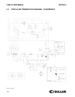
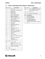
Страница 30: ...1600C LP USER MANUAL SECTION 2 30 2 9 PIPING INSTRUMENTATION DIAGRAM COMPRESSOR 02250176 713 R03 S1 ...
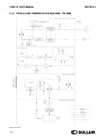
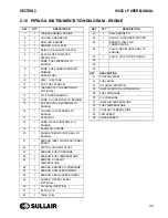
Страница 32: ...1600C LP USER MANUAL SECTION 2 32 2 10 PIPING INSTRUMENTATION DIAGRAM ENGINE 02250176 713 R03 S2 ...
Страница 42: ...42 NOTES ...
Страница 46: ...1600C LP USER MANUAL SECTION 3 46 3 6 ID TANDEM AXLE 02250175 070 r00 ...
Страница 48: ...1600C LP USER MANUAL SECTION 3 48 3 8 ID 4 WHEEL 02250175 073 r00 ...
Страница 50: ...1600C LP USER MANUAL SECTION 3 50 3 9 ID WITHOUT RUNNING GEAR 02250175 075 r01 ...
Страница 52: ...NOTES 52 ...
Страница 56: ...NOTES 56 ...
Страница 68: ...68 NOTES ...
Страница 73: ...NOTES ...