


1600C LP USER MANUAL
SECTION 2
28
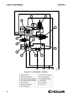
2.6
COMPRESSOR DISCHARGE
SYSTEM, FUNCTIONAL
DESCRIPTION
Refer to
. The Sullair compressor unit
discharges compressed air/fluid mixture into the
receiver tank.
The receiver tank has three functions:
1. It acts as a primary fluid separator.
2. Serves as the compressor fluid storage
sump.
3. Houses the final fluid separator.
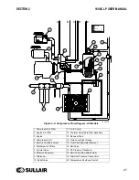
The compressed air/fluid mixture enters the receiver
tank and is directed against the tank side wall. By
change of direction and reduction of velocity, large
droplets of fluid separate and fall to the bottom of the
receiver tank. The fractional percentage of fluid
remaining in the compressed air collects on the
surface of the final separator element as the
compressed air flows through the separator. As more
and more fluid collects on the element surface, the
fluid descends to the bottom of the separator. A
return line (or scavenge tube) leads from the bottom
of the separator element to the inlet region of the
compressor unit. Fluid collecting on the bottom of the
separator element is returned to the compressor by
the pressure difference between the area
surrounding the separator element and the
compressor inlet. An orifice (protected by a strainer)
is included in this return line to help assure proper
flow.
The receiver tank is code rated. A minimum
pressure/check valve, located downstream from the
separator, helps assure a minimum receiver pressure
during all conditions. This pressure is necessary for
proper air/fluid separation and proper fluid
circulation.
A minimum pressure/check valve at the outlet of the
receiver is installed to prevent compressed air in the
service line from bleeding back into the receiver on
shutdown when the compressor is being run in
parallel with other compressors tied to a large air
system.
Fluid is added to the receiver tank via a capped fluid
filler. A fluid level gauge glass enables the operator
to visually monitor the receiver tank fluid level.
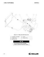
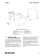
2.7
AFTERCOOLED AIR SYSTEM,
FUNCTIONAL DESCRIPTION
Refer to
. The purpose of the aftercooled
air system is to operate the air compressor in
conditions when compressed air temperatures are
required to be 10 to 25
°
F (5 to 13
°
C) over ambient
temperature. Two discharge valves are provided on
all aftercooled compressor models. One valve is
labeled standard air and one valve is labeled
aftercooled air. Closing the standard air (non-
aftercooled) valve completely forces the air flow from
the receiver tank to the aftercooler. The ambient air,
which is drawn through the aftercooler by the engine
fan, cools the compressed air as it passes through
the aftercooler core. Cooled air enters the moisture
separator where condensation is removed from the
cooler air and discharged. This condensation does
carry some oil and it should be disposed of properly
in accordance with local regulations. A condensation
drain port is located in the frame on the front of the
machine for convenience of condensate removal.
This drain port should never be plugged or closed off
in any way. From the moisture separator the
compressed air goes through the discharge filters (if
equipped) and on to the service valve.
WARNING
DO NOT remove caps, plugs, and/or other
components when compressor is running
or pressurized. Stop compressor and
relieve all internal pressure before doing so.
NOTE
Aftercooled system should not be operated
in ambient conditions below 32°F (0°C). If it
is necessary to operate in these conditions,
Sullair can supply optional equipment to
accommodate this requirement. To operate
in the non-aftercooled mode, close the
aftercooler service valve completely and
open non- aftercooled valve.
Содержание 02250175-949 R01
Страница 2: ......
Страница 20: ...SECTION 1 20 ...
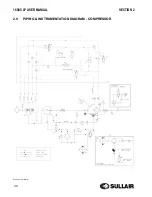
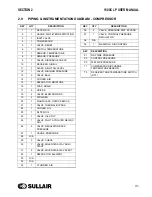
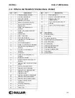
Страница 30: ...1600C LP USER MANUAL SECTION 2 30 2 9 PIPING INSTRUMENTATION DIAGRAM COMPRESSOR 02250176 713 R03 S1 ...
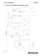
Страница 32: ...1600C LP USER MANUAL SECTION 2 32 2 10 PIPING INSTRUMENTATION DIAGRAM ENGINE 02250176 713 R03 S2 ...
Страница 42: ...42 NOTES ...
Страница 46: ...1600C LP USER MANUAL SECTION 3 46 3 6 ID TANDEM AXLE 02250175 070 r00 ...
Страница 48: ...1600C LP USER MANUAL SECTION 3 48 3 8 ID 4 WHEEL 02250175 073 r00 ...
Страница 50: ...1600C LP USER MANUAL SECTION 3 50 3 9 ID WITHOUT RUNNING GEAR 02250175 075 r01 ...
Страница 52: ...NOTES 52 ...
Страница 56: ...NOTES 56 ...
Страница 68: ...68 NOTES ...
Страница 73: ...NOTES ...