(© Oct, 2007)
Air Technology Systems, Inc.
Compact CW Series Installation, Operation & Maintenance Manual
1-4
1.5 General Design
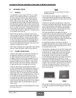
The Compact CW unit is housed in a steel frame type cabinet and is rated for indoor use. The exterior of the
cabinet is coated with a powder coat finish to protect against corrosion. Hinged doors are located in the front of the
cabinet for easy access to all components. Operator controls are conveniently located on the front of the cabinet.
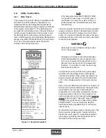
Figure 1 depicts a typical internal layout of a CCD-1800-CW unit and identifies the major components.
1.5.1
Electric Box Access
The electrical components are protected behind the
hinged access door located on the right side of the
unit. The access door is safety interlocked with the
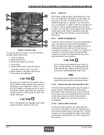
main power service disconnect switch, (See Figure 4),
preventing the door from opening when the switch in
the “On” position. The switch must be turned “Off” to
gain access to the electrical components.
The service disconnect switch may be used to turn the
unit off for emergency shutdown or
during routine
maintenance. The handle of the switch may be locked
in the “Off” position to prevent unintended operation
.
1.5.2
Circuit Breakers / Motor Start Protectors
Individual overload protection is provided by circuit
breaker(s) and motor start protectors. These switches
must be manually re-set once the overload condition is
cleared.
1.5.3
Heaters (Optional)
The precision A/C unit incorporates heaters for re-heating
the supply air, as required to offset the sensible cooling of
the system during the dehumidification cycle, and for the
automatic heating mode. As a standard, electric resis-
tance heating elements are factory installed in the supply
airstream after the cooling coil to heat the supply air.
As an option, hot water re-heat may be selected. A hot
water heating coil is factory installed in the supply air
stream after the cooling coil to heat the supply air. A
valve is provided to control the flow of hot water through
the coil to maintain the correct re-heat temperature.
1.5.4
Coil(s)
The cooling and optional hot water re-heating coils are
aluminum finned/copper tube construction. The coils
are leak tested and cleaned before installation by the
factory.
1.5.5
Blower(s)
The unit is equipped with belt driven centrifugal
blower(s) with forward curved blades. The quantity of
blowers varies depending upon the capacity of the A/C
unit. Each blower is dynamically and statically
balanced to minimize vibration. The blower is con-
tained in a double-width, double-inlet housing. The
blower motor uses dual drive belts.
The blower motors are ODP industrial duty and utilize
permanently lubricated ball bearings. The motor is
mounted on an adjustable base for belt tensioning and
is furnished with an adjustable pitch sheave to change
the blower speed.
Figure 1- Typical Internal Layout
(Model CCD-1800-CW shown for reference)
ELECTRIC HEATERS
(OPTIONAL)
COILS
BLOWER MOTOR
FILTER ACCESS
(DOWNFLOW UNITS)
BLOWER(S)
CONDENSATE PUMP
(OPTIONAL)
AIR PROVING SWITCH & DIRTY
FILTER SWITCH (OPTIONAL)
HUMIDIFIER
(OPTIONAL)
ELECTRIC BOX
CHILLED WATER VALVE
PREFERRED POWER
SELECTOR SWITCH
(OPTIONAL)
Содержание Compact CW Series
Страница 1: ...Oct 2007 Compact CW Series Installation Operation Maintenance Manual Air Technology Systems Inc...
Страница 26: ...Oct 2007 Air Technology Systems Inc Compact CW Series Installation Operation Maintenance Manual NOTES...
Страница 28: ...Oct 2007 Air Technology Systems Inc Compact CW Series Installation Operation Maintenance Manual...
Страница 30: ...Oct 2007 Air Technology Systems Inc Compact CW Series Installation Operation Maintenance Manual...
Страница 32: ...Oct 2007 Air Technology Systems Inc Compact CW Series Installation Operation Maintenance Manual...


