34
INSTALLATION
GB
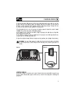
The positive terminal of the battery or of the group of batteries must be connected to one of the
positive terminals of the battery charger. The negative terminal of the battery or of the group of
batteries must be connected to the negative terminal of the battery charger. To make the con-
nections use the cable terminals supplied with the equipment.
If the installation has only one or two groups of batteries, always connect the output marked
“MASTER”. This is the main outlet of the battery charger.
If the “MASTER” is not connected, the battery charger may supply an output lower voltage than
rated and therefore less power.
It is advisable to connect the group of batteries which are used more often (typically the ser-
vice group) to the MASTER output terminal.
The positive output terminals that are not used must be kept free (do not bridge the terminals).
WARNING:
the use of inadequate size cables and the incorrect connection of terminals
or electrical joints may result in dangerous overheating of the connecting terminals or
cables.
8
3
1
6
7
8
9
2
3
4
5
BASIC STATE
C
A
N
1
C
A
N
1
CONTROL SIGNALS
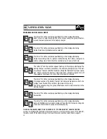
The battery charger is provided with a 9-pin female D-shell connector (DB9 connector, see
Fig. 3a) which indicates the signals which can be used for monitoring and controlling the
equipment.
FIG.3 a
FIG.3 b
Содержание Innotec MBC 12-25/3
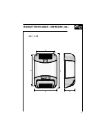
Страница 13: ...205 181 90 135 155 75 MBC BATTERY CHARGER DIMENSIONS mm 12 08 2 12 12 2 11 ...
Страница 14: ...12 268 244 90 135 155 75 MBC BATTERY CHARGER DIMENSIONS mm 12 25 3 24 12 2 ...
Страница 29: ...280 334 272 220 127 MBC BATTERY CHARGER DIMENSIONS mm 12 30 3 12 40 3 27 ...
Страница 30: ...28 358 412 272 220 127 MBC BATTERY CHARGER DIMENSIONS mm 12 60 3 24 30 3 ...
Страница 31: ...REV 000 User s Manual MBC BATTERY CHARGER GB MBC BATTERY CHARGER MBC 12 80 3 MBC 24 60 3 MBC 24 80 3 29 ...
Страница 45: ...447 495 272 220 127 12 80 3 24 60 3 24 80 3 43 MBC BATTERY CHARGER DIMENSIONS mm ...


