background image

37

GB

OPERATING

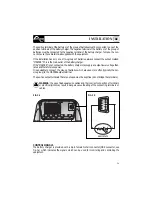
CONTROL PANEL

The control panel is made-up of three LED, a 7 segment display and a button:

POWER LED

,

CHARGE PHASE LED

(BULK, ABSORPTION, FLOAT) 

ERROR LED

,

STATUS 

display

and

ON/STAND-BY 

button (see fig.4).

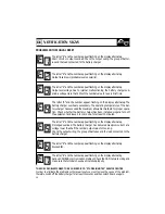
CHARGE PHASE LED

(BULK, ABSORPTION, FLOAT)

ERROR LED

Description

No output power

BULK phase

- charge at constant current

ABSORPTION phase -

charge at constant voltage

FLOAT phase 

- float charge

FIG.4

LED Colour

OFF

Red

Orange

Green

LED Colour

OFF

Red

Description

No problem  with manual reset
Problem with manual reset (see error codes)

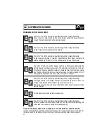
The information supplied by the LEDS are listed as below:

POWER LED 

LED colour

OFF

Green

Flashing

Description

No mains power
Power ON
Battery charger in stand-by mode

ON/STAND-BY BUTTON:

Use this button to put the battery charger in stand-by mode. To activate this mode simply
press the button quickly (press and release in less than one second). To take the battery
charger out of stand-by mode, press the button quickly again or disconnect the battery charg-
er from the AC power supply and then connect it up again.

Содержание Innotec MBC 12-25/3

Страница 1: ...c 13 5 13 8 13 5 13 8 13 5 13 8 13 5 13 8 13 5 13 8 13 5 13 8 Output Amp 8 12 25 30 40 60 Cooling Natural Fan Fan Fan Fan Fan Outputs 2 2 3 3 3 3 Frequency 45 66 Hz 45 66 Hz 45 66 Hz 45 66 Hz 45 66 Hz 45 66 Hz PFC Ambient temp range 20 to 70 C 20 to 70 C 20 to 70 C 20 to 70 C 20 to 70 C 20 to 70 C Dimensions lxwxh mm 155x205x75 155x205x75 155x268x75 272x334x127 272x334x127 272x412x127 Weight kg 1 ...

Страница 2: ...Pag 1 MBC 12 08 2 12 12 2 12 25 3 24 12 2 INDEX Pag 13 MBC 12 30 3 12 40 3 12 60 3 24 30 3 Pag 29 MBC 12 80 3 24 60 3 24 80 3 ...

Страница 3: ...REV 000 User s Manual MBC BATTERY CHARGER MBC BATTERY CHARGER MBC 12 08 2 MBC 12 12 2 MBC 12 25 3 MBC 24 12 2 GB 1 ...

Страница 4: ...on Pag 5 Installation voltage supply batteries Pag 6 Installation Selecting the charging method Pag 7 Operation Control signal Pag 8 Ope characteristics ration Charging Pag 9 Operation Control panel Maintenance Pag 10 Technical data INDEX GB ...

Страница 5: ...MS Compatible with every kind of generator Short circuit overloading output overvoltage and overheating protection Can work in a wide range of ambient temperatures INSTALLATION BEFORE USING THE BATTERY CHARGER CAREFULLY READ THIS USER S MANUAL IN CASE OF DOUBT CONTACT THE STUDER INNOTEC SUPPLIER OR AFTER SALES SERVICE DEPARTMENT THE BATTERY CHARGERS HAS BEEN DESIGNED FOR FIXED INSTALLATIONS FOR IN...

Страница 6: ...ery charger except the base must be kept at a distance from walls or objects by a minimum of 5 cm FIG 1 The cables connected to the output terminals have a maximum length of 4 metres WARNING the battery charger must be used only with a re chargeable lead liquid electrolytic batteries or lead gel sealed or non sealed WARNING the outer surface of the battery charger is used as a heat sink therefore ...

Страница 7: ...connections to an AC supply see fig 2 Before powering up the battery charger check that the power supply voltage described on the rating label corresponds to that supplied by the AC supply source In the electrical circuit a two pole switch must be installed for the sole use of switching the equip ment ON OFF The insulation between the contact points of the connections of the AC supply must be at l...

Страница 8: ...gthen the char ging time FIG 3 a If the installation has only one or two groups of batteries always connect the output marked MAS TER This is the main outlet of the battery charger If the MASTER is not connected the battery charger may supply an output voltage lower than rated It is advisable to connect the group of batteries which are used more often typically the service group to the MASTER outp...

Страница 9: ...present positive SLAVE B output 650mA max By drawing 100mA the error is less than 0 7 Basic state of battery charger 20 mA max Battery charger total current positive shunt 10 mA max The transduction ratio is 100mV 100A GND signal 1 V master GND signal 2 V slave A GND signal 3 V slave B if it present Battery charger total current negative shunt Connection PIN 4 HIGH IMPEDENCE V CHARGE State OFF or ...

Страница 10: ...AT phase FLOAT phase maintenance The battery charger charges the batteries at the constant FLOAT volt age In this phase as the batteries reach maximum capacity they will tend to absorb current close to zero Ampere This FLOAT phase will allow the batteries to be on charge without the risk of overload ing The next step to the ABSORPTION phase occurs when the demand for current goes over 20 of the ma...

Страница 11: ...in output Check output cables the group of batteries and the points of use connected to the battery charger LED Status Description LED Color Off No mains power or overheating In case of overheating check if the installation of the battery charger is correct Switch off and allow the equipment to cool down for at least 10 minutes Power ON Green Description Off Green Green Off Fixed Flashing CHARGE L...

Страница 12: ... Cycoloy Anodized OR5066 155 x 205 x 75 mm 155 x 268 x 75 mm 1 3 Kg 1 4 Kg 2 3 Kg INPUT CHARACTERISTICS PROTECTION Supply voltage 4 Frequency Maximum absorption 230 Vac 6 Maximum absorption 115 Vac 6 CASE Material Colour Dimensions WxHxD Weight Reverse polarity 7 Overload Output short circuit Overheating AMBIENT CHARACTERISTICS Operating temperature Cooling Humidity GENERAL Connector for remote pa...

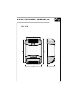
Страница 13: ...205 181 90 135 155 75 MBC BATTERY CHARGER DIMENSIONS mm 12 08 2 12 12 2 11 ...

Страница 14: ...12 268 244 90 135 155 75 MBC BATTERY CHARGER DIMENSIONS mm 12 25 3 24 12 2 ...

Страница 15: ...REV 001 MBC BATTERY CHARGER MBC 12 30 3 MBC 12 40 3 MBC 12 60 3 MBC 24 30 3 User s Manual MBC BATTERY CHARGER GB 13 ...

Страница 16: ... batteries Pag 18 Installation Selecting the charging method Pag 19 Operation Control signal Pag 20 Operation Charging characteristics Pag 21 Operation Control panel Pag 22 23 Notification signs Pag 24 25 Programming the battery charger Pag 26 Maintenance Technical data INDEX GB ...

Страница 17: ...V RMS Universal AC supply input 280 83 Vac 45 66 Hz Power factor cos ϕ equal to 1 Compatible with every kind of generator Short circuit overloading output overvoltage and overheating protection Can work in a wide range of ambient temperatures Variable speed for the cooling fan High technology control panel Automatic and manual half power mode CAN BUS interface for data transfer Case constructed in...

Страница 18: ...ool the equipment The perimeter of the battery charger except the base must be kept at a distance from walls or objects by a minimum of 5 cm CHARACTERISTICS AND INSTALLATION GB The cables connected to the output terminals have a maximum length of 4 metres WARNING the battery charger must be used only with a re chargeable lead liquid electrolytic batteries or lead gel sealed or non sealed 16 FIG 1 ...

Страница 19: ...fore powering up the battery charger check that the power supply voltage de scribed on the rating label corresponds to that supplied by the AC supply source In the electrical circuit a two pole switch must be installed for the sole use of switching the equipment ON OFF The insulation between the contact points of the connections of the AC supply must be at least 3 mm The connections to the AC supp...

Страница 20: ...ry charger may supply an output lower voltage than rated and therefore less power It is advisable to connect the group of batteries which are used more often typically the ser vice group to the MASTER output terminal The positive output terminals that are not used must be kept free do not bridge the terminals WARNING the use of inadequate size cables and the incorrect connection of terminals or el...

Страница 21: ...nterface connection CANH and CANL signals use an unscreened cable with a twisted pair cross section 0 25 0 35 mm2 AWG 22 24 impedance 100 150 ohm The maximum total length of the data signal cable should be no more than 100 m Activate the terminator at the first and last device connected to the network If there is only one device the terminator does not need to be activated An example of a network ...

Страница 22: ...r 97 Vac the battery charger will activate the half power mode In this mode the battery charger can supply a maximum value half of the maximum nominal output current In this way you can reduce the current absorption from the AC supply This feature is useful when the battery charger is supplied via a generator or from a dock outlet with limited power output The half power mode can be activated manu...

Страница 23: ...ange Green LED Colour OFF Red Description No problem with manual reset Problem with manual reset see error codes The information supplied by the LEDS are listed as below POWER LED LED colour OFF Green Flashing Description No mains power Power ON Battery charger in stand by mode ON STAND BY BUTTON Use this button to put the battery charger in stand by mode To activate this mode simply press the but...

Страница 24: ...hich caused the problem is no longer present If this message appears frequently check whether the battery charger has been installed properly The temperature measured by the battery sensors optional is outside the range determined for the charge 20 55 C The output voltage of the battery charger becomes 12 8V 25 6V in the 24V models so that the batteries are not damaged This message disappears when...

Страница 25: ...era tion Check whether the battery charger has been installed properly Turn off the equipment and leave it to cool down for at least 10 minutes The letter E and the number appear flashing on the display alternately Prolonged overload The battery charger has delivered maximum current at a voltage lower than half the nominal output value for too long Check the output wiring the group of batteries an...

Страница 26: ...ion is made this could reduce the service life of the batteries or mean the charging time takes longer The letter liquid Electrolyte or gel will appear flashing on the display according to the current setting To change the setting press the key quickly press and release the button in less than 1 second To make the setting operative press the key for at least 2 seconds The display will confirm the ...

Страница 27: ...ing operative press the key for at least 2 seconds The display will confirm the setting by showing the number selected for one second steady Once the programming procedure has been completed the following symbol will be shown for 1 second ACTIVATING INACTIVATING THE MONITOR MODE This function enables the user to activate or inactivate the battery charger s monitor mode If it is activated the monit...

Страница 28: ...Kg 5 4 kg INPUT CHARACTERISTICS PROTECTION Supply voltage Frequency Maximum absorption 230 Vac 4 Maximum absorption 115 Vac 4 Power factor cos ϕ CASE Material Colour Dimensions WxHxD Weight Reverse polarity 5 Overload Output short circuit Overvoltage in output 6 Overheating Battery overtemperature AMBIENT CHARACTERISTICS Operating temperature Cooling Humidity GENERAL Connector for remote panel Saf...

Страница 29: ...280 334 272 220 127 MBC BATTERY CHARGER DIMENSIONS mm 12 30 3 12 40 3 27 ...

Страница 30: ...28 358 412 272 220 127 MBC BATTERY CHARGER DIMENSIONS mm 12 60 3 24 30 3 ...

Страница 31: ...REV 000 User s Manual MBC BATTERY CHARGER GB MBC BATTERY CHARGER MBC 12 80 3 MBC 24 60 3 MBC 24 80 3 29 ...

Страница 32: ...ply batteries Pag 32 Installation Selecting the charging method Pag 33 Operation Control signal Pag 35 Operation Charging characteristics Pag 36 Operation Control panel Pag 37 38 Notification signs Pag 39 40 Battery charger programming Pag 41 Maintenance Technical data INDEX GB ...

Страница 33: ...mV RMS Universal AC supply input only MBC 12 80 8 Power factor cos ϕ equal to 1 Compatible with every kind of generator Short circuit overloading output overvoltage and overheating protection Can work in a wide range of ambient temperatures Variable speed for the cooling fan High technology control panel Automatic and manual half power mode CAN BUS interface for data transfer Case constructed in s...

Страница 34: ...heat helps to cool the equipment The perimeter of the battery charger except the base must be kept at a distance from walls or objects by a minimum of 5 cm CHARACTERISTICS AND INSTALLATION GB The cables connected to the output terminals have a maximum length of 4 metres WARNING the battery charger must be used only with a re chargeable lead liquid electrolytic batteries or lead gel sealed or non s...

Страница 35: ...fore powering up the battery charger check that the power supply voltage de scribed on the rating label corresponds to that supplied by the AC supply source In the electrical circuit a two pole switch must be installed for the sole use of switching the equipment ON OFF The insulation between the contact points of the connections of the AC supply must be at least 3 mm The connections to the AC supp...

Страница 36: ...ry charger may supply an output lower voltage than rated and therefore less power It is advisable to connect the group of batteries which are used more often typically the ser vice group to the MASTER output terminal The positive output terminals that are not used must be kept free do not bridge the terminals WARNING the use of inadequate size cables and the incorrect connection of terminals or el...

Страница 37: ... data interface connection CANH and CANL signals use an unscreened cable with a twisted pair cross section 0 25 0 35 mm2 AWG 22 24 impedance 100 150 ohm The maximum total length of the data signal cable should be no more than 100 m Activate the terminator at the first and last device connected to the network If there is only one device the terminator does not need to be activated An example of a n...

Страница 38: ...r 97 Vac the battery charger will activate the half power mode In this mode the battery charger can supply a maximum value half of the maximum nominal output current In this way you can reduce the current absorption from the AC supply This feature is useful when the battery charger is supplied via a generator or from a dock outlet with limited power output The half power mode can be activated manu...

Страница 39: ...ange Green LED Colour OFF Red Description No problem with manual reset Problem with manual reset see error codes The information supplied by the LEDS are listed as below POWER LED LED colour OFF Green Flashing Description No mains power Power ON Battery charger in stand by mode ON STAND BY BUTTON Use this button to put the battery charger in stand by mode To activate this mode simply press the but...

Страница 40: ...hich caused the problem is no longer present If this message appears frequently check whether the battery charger has been installed properly The temperature measured by the battery sensors optional is outside the range determined for the charge 20 55 C The output voltage of the battery charger becomes 12 8V 25 6V in the 24V models so that the batteries are not damaged This message disappears when...

Страница 41: ...ther the battery charger has been installed properly Turn off the equipment and leave it to cool down for at least 10 minutes The letter E and the number appear flashing on the display alternately Prolonged overload The battery charger has delivered maximum current at a voltage lower than half the nominal output value for too long Check the output wiring the group of batteries and the load connect...

Страница 42: ... selec tion is made this could reduce the service life of the batteries or mean the charging time takes longer The letter liquid Electrolyte or gel will appear flashing on the display according to the current setting To change the setting press the key quickly press and release the button in less than 1 second To make the setting operative press the key for at least 2 seconds The display will conf...

Страница 43: ...ing operative press the key for at least 2 seconds The display will confirm the setting by showing the number selected for one second steady Once the programming procedure has been completed the following symbol will be shown for 1 second ACTIVATING INACTIVATING THE MONITOR MODE This function enables the user to activate or inactivate the battery charger s monitor mode If it is activated the monit...

Страница 44: ...ISTICS Maximum output current 1 Charge absorption voltage Charge float voltage Residual ripple 2 Charging characteristics Number of outputs 3 80 A 60 A 80 A 14 1 Vdc 14 4 Vdc GEL 28 2 Vdc 28 7 Vdc GEL 13 5 Vdc 13 8 Vdc GEL 27 0 Vdc 27 5 Vdc GEL 90mV RMS max Automatica a tre stadi IUoU 3 Yes through fuse Yes Yes Yes Yes Yes optional 83 280 Vac with power 150 280 Vac with power reduction under 195 V...

Страница 45: ...447 495 272 220 127 12 80 3 24 60 3 24 80 3 43 MBC BATTERY CHARGER DIMENSIONS mm ...

Страница 46: ...STUDER INNOTEC RUE DES CASERNES 57 1950 SION SWITZERLAND TEL 41 0 27 205 60 80 FAX 41 0 27 205 60 88 www studer inno com E mail info studer inno com ...

Отзывы: