Stryker PneumoSure Скачать руководство пользователя страница 50

48

EN

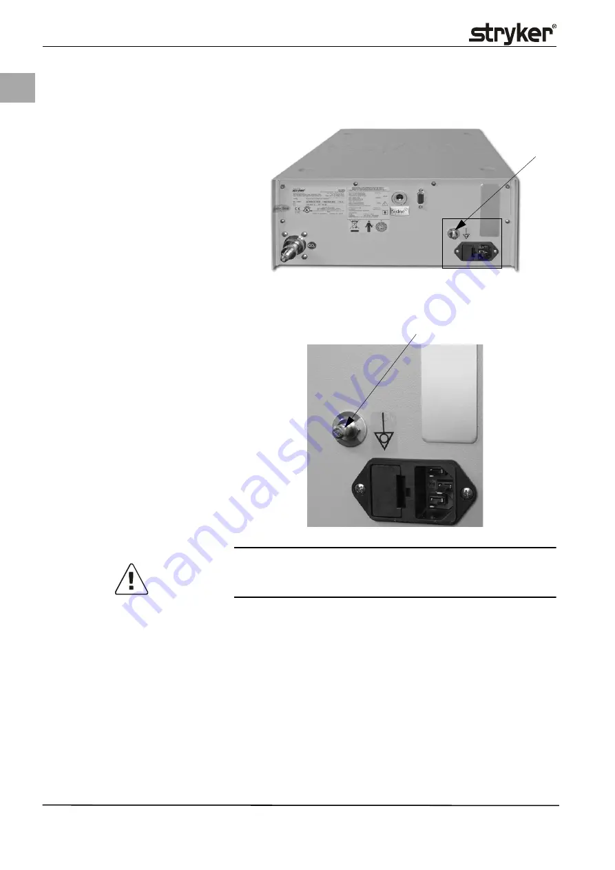
Replacing Components and Modules 

6.7

Uninstalling/Installing Potential equalization MC-Plug

DANGER!

Disconnect device from power supply.

1. Remove power connection cable from mains socket.
2. Use a size 10 socket wrench to remove the potential equalization plug 

(1)

from the rear panel of the device. 

3. Follow these steps in reverse for assembly.

Perform the following tests after installing the new component:

• Electrical safety test (see chapter 4.1 Safety Test).

Fig. 6-14 Position of potential equaliza-

tion plug 

(1)

Potential equalization plug

A

(1)

Fig. 6-15 Detail A: Potential equalization 

plug

(1)

Potential equalization plug

A

(1)

Содержание PneumoSure

Страница 1: ...EN DE 2007 09 www stryker com 1000 xxx xxx Rev A Service Manual Service Handbuch Insufflator for Laparoscopy and Vessel Harvesting P R E L I M I N A R Y C O P Y ...

Страница 2: ...rvielfältigt oder verbreitet werden Durch die ständige Weiterentwicklung unserer Produkte behalten wir uns tech nische Änderungen ohne Ankündigung vor Funktion oder Design können teil weise von der Beschreibung im Handbuch abweichen Bitte kontaktieren Sie uns um weitere Informationen zu diesem oder anderen Produkten zu erhalten Bezeichnungen die zugleich eingetragenes Warenzeichen sind wurden nich...

Страница 3: ...ure Alarm 20 4 10 Testing the Occlusion Warning 21 4 11 Fluid Sensor Test 22 5 Service Menu 23 5 1 Service Menu Access 24 5 2 Service Menu Overview 25 5 3 Touch Display Calibration 26 5 4 Offset Calibration 27 5 5 LOW Pressure Calibration 28 5 6 HIGH Pressure Calibration 29 5 7 LPR Calibration 30 5 8 Flow Calibration 31 5 9 LSV Calibration 32 5 10 12 hr Test 33 5 11 Resetting to Factory Defaults 3...

Страница 4: ... 16 Uninstalling Installing Tube Detection 61 6 17 Uninstalling Installing Snap Lock 62 6 18 Uninstalling Installing Touch Display 64 7 Spare Parts List 67 8 Error and Warning Messages 68 9 Technical Data 70 10 Abbreviations 71 11 Appendix 72 11 1 Service and Checklist 72 ...

Страница 5: ...mages and the warranty becomes null and void if the device or the accessories are used improperly the instructions and rules in the manual are not adhered to the device or the accessories are improperly prepared or maintained unauthorized persons perform repairs adjustments or alterations on the de vice or accessories the prescribed inspection and maintenance schedules are not adhered to The servi...

Страница 6: ...hanical skills Stryker service technician certificate 2 2 Tools and Test Equipment Make sure the measuring instruments are calibrated and in perfect working or der before starting any maintenance tasks The following tools and measuring in struments must be kept readily available Multimeter Voltage up to 1000 V AC DC electric current 10 A with ohmmeter and continuity tester ESD protective mat antis...

Страница 7: ...wing supplemental tools test resources and measurement instruments are required to perform the service and maintenance routines described in this manual Calibration adapter T adapter 6x6x6 mm with venting valve Internet access for software update via GlobalServices net www womser vice com ...

Страница 8: ...m Hg LSV 7 High pressure temperature sensor HTS 23 Fluid sensor FLS 8 High pressure safety valve 3 5 bar 24 Connection for RTP system 9 Gas heating for high pressure unit HPH 25 Insufflation tube connection 10 Low pressure unit LPU 26 Heater coil for gas heating 11 Low pressure regulator 120 mm Hg LPR 27 Temperature sensor for gas heating 12 Patient pressure valve PPV 28 Loudspeaker 13 Median pres...

Страница 9: ...wer supply unit 12 ON OFF power switch 3 Power supply controller board 13 Display touch panel 4 Fuse holder 14 Faceplate 5 Mains socket 15 Con rods 6 SIDNE interface optional 16 NET board power switch 7 Potential equalization MC plug USA 17 Low pressure unit LPU 8 Gas connection US 18 BAM board 9 Lower part of case 19 IFM board optional 10 High pressure unit HPU ...

Страница 10: ...8 EN Device Setup 3 3 Pneumo Sure Wiring Diagram ...

Страница 11: ...er switch 2 Display touch panel LCD 3 Tube connection 4 Case lid 1 2 3 4 Fig 3 2 Rear view of the device 1 Type plate 2 Device data plate 3 SIDNE interface 4 Service interface 5 Potential equalization plug 6 Mains socket 7 Fuse holder 8 Gas supply connection US 9 Service seal CO2 9 8 7 6 1 2 3 4 5 ...

Страница 12: ...low the steps depicted in Fig 3 3 a Turn the four Phillips screws 2 counterclockwise to remove them from the rear of the device b Slightly lift the case lid 1 and pull off approx 3 cm towards rear c Remove case lid 1 completely by lifting up Follow these steps in reverse for assembly Fig 3 3 Opening the device 1 Case lid 2 4x Phillips screws 1 2 a b b c ð ...

Страница 13: ...ompany together wit the signature of the service technician 4 1 Safety Test A safety test has to be carried out by a trained technician within the scope of the annual inspection A visual inspection must be performed Of particular importance is that the fuse corresponds with the specifications indicated by the manufacturer labels and stickers on device are legible the mechanical condition of the de...

Страница 14: ...ilter 3 may be plugged or soiled due to unclean gas or gas supply residues see Fig 4 1 Gas supply connection This type of soiling however can not be detected externally Heavy soiling is especially noticeable during higher flow rates and results in the actual gas flow falling short of the nominal gas flow during active insufflation If cleaning the surface of the gas inlet filter does not yield any ...

Страница 15: ...mum supply pressure 3 While device is switched on and the gas bottle is connected and opened pull plug ST3 cable 3 of the high pressure sensor off the PCU board 4 4 In the display the error message Check gas supply must be depicted The gas supply display depicts a pressure of 15 bar Reconnect plug connector 3 with PCU board 4 5 The test of the high pressure sensor has been completed successfully C...

Страница 16: ...e additionally connected outlet valve A stable end value of 1 5 to 2 5 bar must be reached NOTE The output value drops with an increasing temperature e g long operation time and has to be adjusted if necessary Remove the test equipment and reinsert the high pressure tube 2 or continue with chapter 4 6 4 Checking High Pressure Unit HPU for Leaks Corrective measure Use the adjustment screw 3 at the ...

Страница 17: ...10 minutes the pressure at the 0 7 bar manometer should not have dropped more than 5 bar Corrective measure Checking gas supply connection O ring Replacing the high pressure unit HPU 4 6 5 Checking the High Pressure Heating Unit Fig 4 5 High pressure unit HPU 1 High pressure unit HPU 2 Plastic ring 3 High pressure tube HPT 1 2 3 press pull Fig 4 6 Position of high pressure heat ing unit HPH 1 High...

Страница 18: ...eater 3 and or the LPU have to be replaced see chapter 6 2 1 Replacing the Heater Tem perature Sensor and chapter 6 3 Uninstalling Installing Low Pressure Unit LPU When installing the heater 3 make sure it is placed completely on the insulat ing foil 5 Attach heater 3 with the fastening screw 4 and a plastic insulat ing bush 4 6 6 Checking High Pressure Safety Valve HSV at the HPU Replace the HPU ...

Страница 19: ...ervice manual require mounting of a calibration adapter This adapter consists of a calibration tube with connection plug a T adapter with 3 port valve and 2 emerging tubes 1 Slide plug of the calibration tube into tube connection of the device until locked into place 2 Turn the Allen screw clockwise using a size 4 Allen wrench up to the stop 3 Connect the corresponding supplementary equipment to t...

Страница 20: ...seconds Corrective measure Check the calibration adapter for leaks by clamping off the tube leading to the tube connection at the LPU 7 using a tube clamp and carrying out a leak test once more If another leak is detected check the correct fit of the connection adapter seal and check all tube connections of the adapter including those of the 3 port valve Replace the LPU if the calibration adapter ...

Страница 21: ...Maintenance and Service Tasks 19 EN Fig 4 11 Position of fluid sensor low pressure tube LPT 6 Fluid sensor tube connection 7 Low pressure unit LPU tube con nection 6 7 ...

Страница 22: ...15 mm Hg nomi nal flow 3 l min 5 Use the syringe to slowly generate a pressure of 15 mm Hg 6 Slowly increase the pressure to 20 mm Hg and then press the START STOP key 7 A warning sound is emitted and Overpressure is depicted 8 Set the gas flow to 5 l min and the nominal pressure to 21 mm Hg 9 After max 5 seconds the venting system will be activated depends on the time and pressure threshold set i...

Страница 23: ...valve 2 to the depict ed position 3 Start insufflation with the START STOP key 4 An audible warning signal is emitted and Occlusion is depicted note The acoustic warning signal can be deactivated in the user menu 5 Turn the 3 port valve to the right by 90 The warnings are deactivated 6 End insufflation with the START STOP key Corrective measure Check for leaks to make sure the calibration adapter ...

Страница 24: ...e message Contamination alternating with Call service 6 Reattach the ST6 plug to the PCU board 7 Turn device off and on again 8 Open the service menu of the device and delete the contamination alarm see chapter 5 14 Deleting Contamination 9 Turn device off and on again The contamination alarm must be disabled Corrective measure If the device does not respond the way described above the fluid senso...

Страница 25: ...splay Confirm input by pressing the SAVE key A step back or exiting the menu level is carried out with the EXIT key When using the calibration adapter note the mounting instructions as de scribed in chapter 4 7 Mounting the Calibration Adapter Always make sure the 3 port valve is positioned correctly when using the cali bration adapter as depicted in the corresponding illustration Always follow th...

Страница 26: ...24 EN Service Menu 5 1 Service Menu Access ...

Страница 27: ...Service Menu 25 EN 5 2 Service Menu Overview 5 3 Chapter 5 4 5 5 5 11 5 14 5 6 5 7 5 8 5 9 5 10 5 12 5 13 ...

Страница 28: ...ocess by touching the touch display any where on screen for 2 seconds during the device self test Tapping the two black crosshairs on the display see Fig below is part of the calibration process Con firm the calibration with the SAVE key Please note that the calibration described here is only temporary The actual calibration must be carried out in the service menu ...

Страница 29: ...Service Menu 27 EN 5 4 Offset Calibration Fig 5 1 Test setup Offset calibration 1 Flowmeter 0 50 slpm 2 Tube small diameter 3 Three port valve 4 Calibration adapter mm Hg 4 1 2 3 ...

Страница 30: ... EN Service Menu 5 5 LOW Pressure Calibration Fig 5 2 Test setup LOW pressure cali bration 1 Manometer 0 100 mm Hg 2 Calibration adapter 3 Flowmeter 4 LSV regulator low pressure safety valve mm Hg 2 1 3 4 ...

Страница 31: ...Service Menu 29 EN 5 6 HIGH Pressure Calibration Fig 5 3 Test setup HIGH pressure cali bration 1 Manometer 0 100 bar 2 Gas bottle pressure 50 bar CO2 CO2 1 2 ...

Страница 32: ...30 EN Service Menu 5 7 LPR Calibration Fig 5 4 Setting of low pressure regula tor LPR 1 Open tube end tube with small diameter 2 Calibration adapter 3 LPR regulator 4 LSV regulator 2 1 3 4 ...

Страница 33: ...Service Menu 31 EN 5 8 Flow Calibration Fig 5 5 Test setup Flow calibration 1 Flowmeter 0 50 slpm 2 Calibration adapter mm Hg 2 1 ...

Страница 34: ...32 EN Service Menu 5 9 LSV Calibration Fig 5 6 Test setup Low pressure safety valve LSV 1 Calibration adapter 2 LSV regulator mm Hg 1 2 ...

Страница 35: ...ave to be selected in order to calibrate or service the device When conducting the 12 hr test make sure the device is continuously connected to a hot power supply and is not used or operated otherwise Switch device off and on again after completing the 12 hr test ...

Страница 36: ...se note that selecting this menu option will restore all factory settings The device is then not calibrated and cannot be used until recalibrated Prerequisites Device in service mode Confirm with SAVE Press key until display depicts Factory default EXIT Confirm with SAVE Factory default Service please wait Factory default Calibration success Factory default Factory default Service Display ...

Страница 37: ...Service Menu 35 EN 5 12 Viewing Program Version Use this menu option also to view the current software versions of the BAM PCU MIO and IFM boards optional ...

Страница 38: ...36 EN Service Menu 5 13 Viewing Customer Version Use this menu option to view the current customer versions of the BAM PCU MIO and IFM boards optional ...

Страница 39: ...leting the contamination alarm WARNING Canceling a contamination alarm is only permissible if this alarm was triggered by an erroneous manipulation or during service or maintenance tasks e g by pulling a plug or during cleaning The contamination alarm is not canceled until after the device has been restarted If the contamination alarm was triggered while using the device with a patient it is not p...

Страница 40: ...38 EN Service Menu ...

Страница 41: ...n tests after replacing a component or part The following components modules can be replaced in case of a defect Fluid sensor complete Gas connection USA Case lid Lower part of case incl device pads Pneumo Sure front High pressure unit HPU complete Heater temperature sensor for for high pressure unit component Insufflator Pneumo Sure set of cables complete Mains socket with fuse holder Mains switc...

Страница 42: ...y mounted with Gas inlet filter sintered metal filter 4 Screw connection SW24 3 O ring at face surface 6 Fig 6 1 Position of gas supply connec tion 1 Gas supply connection A 1 Fig 6 2 Detail A Gas supply connec tion 2 4x fastening screws 3 Wrench flat WS24 4 Gas inlet filter sintered metal A 2 2 3 4 Fig 6 3 Gas supply connection disas sembled 5 Anti twist stop 6 O ring seal 5 6 ...

Страница 43: ... O ring remains in place when removing the component 6 NOTE When inserting the new gas supply connection make sure to insert the anti twist stop 5 properly 6 2 Uninstalling Installing High Pressure Unit HPU The gas connection is connected with the high pressure unit The high pressure unit consists of the following function elements High pressure regulator High pressure safety valve High pressure s...

Страница 44: ... new HPU high pressure unit Testing the HPU for leaks see 4 6 4 Checking High Pressure Unit HPU for Leaks Offset calibration see chapter 5 4 Offset Calibration HIGH pressure calibration see chapter 5 6 HIGH Pressure Calibration 6 2 1 Replacing the Heater Temperature Sensor To replace the heater temperature sensor 5 the high pressure unit HPU must be removed Heater and temperature sensor are combin...

Страница 45: ...ee also Fig 4 5 High pressure unit HPU 5 Use a SW 4 socket wrench to remove the four fastening nuts 6 and lift out the entire unit by pulling straight up 6 Follow these steps in reverse for assembly The following tests updates must be performed after installing a new low pres sure unit LPU Software update via Global Services net Testing the Low Pressure Unit LPU for Leaks Basic function test Safet...

Страница 46: ...lve 2 PCU board 3 3x fastening screws 4 ST8 plug cable leading to PCU 5 2x tube connection PPV 3 4 3 1 2 5 Fig 6 8 Tube connection variation A 6 LPU tube connection 7 PPV tube connection 8 PPV valve 9 PPV tube connection 10 Tube connection pressure sensor PPS PCU board 11 Tube connection for RTP system 9 8 6 7 10 11 ...

Страница 47: ...bes are not kinked or clamped in any way when installing the PPV valve Two dif ferent tube connection variations are possible see Fig 6 8 Tube connection variation A and Fig 6 9 Tube connection variation B Align and position the tubes as depicted in the illustration when replacing these tubes When con necting to the pressure sensor 10 make sure to connect the tube to the up per connection The foll...

Страница 48: ... nuts washers 3 and lift off the power supply board by pull ing up 7 Follow these steps in reverse for assembly The following tests have to be performed after installing a new power supply unit Connect to the power supply and turn on device Use a multimeter to check the voltage of the power supply unit at the input plug 6 100 240 V and at the output plug 4 24V Perform a safety test as described in...

Страница 49: ...ing to the NET board 3 Pull ST2 plug from NET board see also Fig 6 20 Detail A Power switch NET board 4 Remove ground wire connection cable 5 from bottom of case 5 Remove the two fastening screws 3 from the outer rear panel and remove the mains socket with the cables by pulling towards back 6 Follow these steps in reverse for assembly The following tests must be performed after installing a new ma...

Страница 50: ...cket wrench to remove the potential equalization plug 1 from the rear panel of the device 3 Follow these steps in reverse for assembly Perform the following tests after installing the new component Electrical safety test see chapter 4 1 Safety Test Fig 6 14 Position of potential equaliza tion plug 1 Potential equalization plug A 1 Fig 6 15 DetailA Potentialequalization plug 1 Potential equalizatio...

Страница 51: ...oard by pulling towards side 6 Remove MIO LCD board by pulling up from the board bracket 7 Remove the fastening nuts 1 and lift out the MIO board 8 Follow these steps in reverse for assembly Perform the following tests calibrations after installing the new component Fig 6 16 Position of MIO MIO LCD board 1 4x fastening screws 2 MIO board 3 Plug ST1 cable leading to touch display 4 ST6 plug cable l...

Страница 52: ...1 by sliding carefully between latch 10 and plug 11 with your fingernail Pull flat ribbon cable for LCD Note When reinstalling the components make sure the flat ribbon cable is insert ed straight into the open latch and up to the stop Do not insert the flat ribbon cable between plug and circuit board make sure you insert the ribbon cable properly into the corresponding connector Then close the lat...

Страница 53: ...the two board latches from the board and pull out the board until it extends slightly towards top 5 Remove the ST2 plug 6 and ST4 plug 5 from the BAM board by pulling ver tically 6 Completely remove BAM board 4 from device 7 Follow these steps in reverse for assembly Perform the following tests updates after installing the new component Software update via Global Services net Basic function test S...

Страница 54: ... A Power switch NET board 2 Plug ST2 cable leading to mains socket 3 ST1 plug cable leading to PSM power supply unit board 4 ST3 plug cable leading to BAM board 5 Dummy plug 6 ST4 plug cable leading to power switch LED 7 2x fastening screws A 2 3 4 6 7 5 Fig 6 21 Mains switch 8 Guide for power switch 9 Power switch with LED 10 Cable for LED 11 Stay bolts for NET board 8 9 10 11 ...

Страница 55: ...d into the opening at the front of the device and clicks into place with two lateral pins These pins are visible through notches in the guide The power switch knob can be popped out by carefully pinching these pins together and applying axial pressure at the same time The LED is glued into the power switch knob and thus forms one unit When replacing the NET board or the power switch knob make sure...

Страница 56: ... of SIDNE interface 1 Ring nut 2 SIDNE interface 1 2 Fig 6 24 SIDNE interface rear device panel inside 3 Capacitor connection 4 Cable leading to IFM board 3 4 Fig 6 25 Position of IFM board 5 Board latch 6 IFM board 7 ST1 plug flat ribbon communica tion cable 8 ST2 plug cable leading to SIDNE interface 5 5 6 7 8 ...

Страница 57: ...e steps in reverse for assembly The following tests updates must be performed after installing a new IFM board Software update Basic function test Safety test see chapter 4 1 Safety Test Uninstalling installing the SIDNE interface 1 Remove cable of the capacitor 3 from the rear of the device panel 2 Remove the ST2 plug 8 from the IFM board 3 Unscrew the ring nut 1 at the outside of the rear device...

Страница 58: ...ove the ST1 plug cable 2 from the rear HPL board 1 by pulling paral lel to the top 4 Unscrew the two fastening screws 3 and remove the HPL board Make sure the O ring remains in place when removing the component 5 Follow these steps in reverse for assembly Make sure the O ring is in place when installing the component The following tests must be performed after installing a new HPL board Fig 6 27 P...

Страница 59: ...e PCU board 6 by pulling towards side 3 Use a SW 2 Allen wrench to remove the setscrew 1 and remove the sleeve in 2 axial direction 4 Remove the low pressure tube at position 4 5 Follow these steps in reverse for assembly The following tests must be performed after installing a new fluid sensor Leak test see chapter 4 8 Testing the Low Pressure Unit LPU for Leaks Fluid sensor test see chapter 4 11...

Страница 60: ...his can be done with the help of a hex key or Allen wrench for example inserted into the hole of the con rod 5 Remove fluid sensor from tube connection as described in chapter 6 13 Unin stalling Installing Fluid Sensor 6 Remove the patient pressure measurement tube at position 6 7 Remove the plug ST4 cable leading to the power switch LED from the NET Fig 6 30 Position of device front 1 Device fron...

Страница 61: ...nt Basic function test Safety test see chapter 4 1 Safety Test The device front panel is to be removed when replacing the MIO or HPL board or the touch display the tube connection and the tube detection to ensure proper access to these components 6 15 Uninstalling Installing Tube Connection Fig 6 32 Position of tube connection 1 Snap lock 2 Patient pressure measurement connection 3 Tube connection...

Страница 62: ...be connection 6 counterclockwise using the as sembly key 8 to remove from tube connection threading and take the tube connection out off the device front 5 Follow these steps in reverse for assembly Make sure the correct turning di rection is observed during installation see Fig 6 32 Position of tube connec tion The following tests must be performed after installing a new tube connection Basic fun...

Страница 63: ...rd MIO LCD 5 Remove adhesive copper tape from device front see Fig 6 43 Remove face plate page 65 6 Carefully press the six catches plastic into the frame so that the faceplate plastic can be removed from the device front see Fig 6 43 Remove face plate page 65 7 Remove the light sensor from the faceplate see Fig 6 40 Position of touch display page 64 8 Remove the ST6 plug cable leading to the tube...

Страница 64: ...ered lis ten for a clicking sound If this is not the case set the trigger sensitivity of the tube detection as described in section 2 and 3 2 Set the distance of the micro switch to the plunger by turning the setting screw 8 until the micro switch is triggered listen for clicking sound 3 Then tighten the locknut screw 7 in place The following tests must be performed after installing a new tube det...

Страница 65: ...nd right of the snap lock 4 towards the outside to remove snap lock 4 from device front 4 Follow these steps in reverse for assembly Make sure the snap lock 2 is po sitioned correctly when installing see Fig 6 38 Detail A Snap lock The following tests must be performed after installing a new snap lock Basic function test Safety test see chapter 4 1 Safety Test Fig 6 39 Snap lock rear 3 Clamping pl...

Страница 66: ...uare 2 Display touch panel 3 Cable leading to MIO board 4 Device front without faceplate 5 Light sensor for MIO board tube detection 6 Metallic stops 1 2 3 5 4 6 Fig 6 41 Touch display rear 7 Display touch panel 8 ST1 plug cable leading to MIO board 9 Flat ribbon cable LCD 7 9 8 Fig 6 42 Flat ribbon cable LCD 10 Flat ribbon cable LCD 10 ...

Страница 67: ...emove faceplate 11 6x catches faceplate 12 Adhesive copper tape 11 11 11 12 Fig 6 44 Flat ribbon cable LCD latch 13 Flat ribbon cable LCD 14 LCD latch 15 Blue marking 13 15 14 Fig 6 45 Light sensor fastening 16 Faceplate 17 Touch display 18 Light sensor 19 Adhesive cloth tape black 16 19 17 18 ...

Страница 68: ... these steps in reverse for assembly Follow these steps to install a touch display 1 Flip the latch 14 up and insert the LCD flat ribbon cable 13 with the blue marking 15 pointing up into the latch Flip latch down to fix flat ribbon ca ble in place 2 Carefully shape the LCD flat ribbon cable 10 by bending according to Fig 6 42 Flat ribbon cable LCD 3 Place the touch display on the front panel and ...

Страница 69: ...tch assembly 2201317 Power control board Pneumo Sure NET board 2203122 Display touch panel 2203134 Heater temperature sensor 2200892 SMD fuse 2 A super fast acting for PCU heater 2201798 O ring seal for gas supply connection 2201377 Gas connection US 2200694 Snap lock 2203132 Pneumo Sure fluid sensor 2203118 Tube connection 2203129 Tube detection 2203130 PPV valve 2203128 Insufflator Pneumo Sure s...

Страница 70: ...ssure sensor too high Replace LPU 22 Offset safety pressure sensor too high Replace LPU 23 Offset differential pressure sensor too high Replace LPU 24 Offset high pressure sensor too high Replace HPU 25 Offset temperature sensor too high Replace LPU 26 Offset current monitor of high pressure gas heating too high Replace LPU 27 Offset high pressure gas heating too high Replace LPU or heater 50 Gene...

Страница 71: ... General calibration error low pressure safety valve Replace LPU 111 Adjustment low pressure safety valve not within range Repeat calibration 130 General error flow Check flowmeter replace LPU 131 Flow resistance too high Check flowmeter replace LPU 133 Flow input value too low Replace LPU 134 Flow input value too high Replace LPU 135 Modified flow sensor value Replace LPU 136 Flow sensor amplific...

Страница 72: ... 10 85 rel humidity 85 100 rel humidity 14 days Manufactured and tested accord ing to EN 60601 1 EMC EN 60601 1 2 Insufflation medium Medical CO2 Maximum output pressure 75 mm Hg 1 mm Hg 1 33 mbar 133 Pa Maximum gas supply pressure 80 bar 1160 PSI Minimum gas supply pressure bot tle 15 bar 218 PSI Minimum gas supply pressure house gas 3 4 bar 50 PSI Measurement range of gas supply 0 50 bar 0 725 P...

Страница 73: ...nterface module LCD Display touch panel LPT Low pressure tube LPR Low pressure regulator LPU Low pressure unit LSV Low pressure safety valve MIO Multi input output module MSV Median pressure safety valve NET Mains switch OLV Outlet valve PCU Pneumatic control unit PMS Pressure measuring sensor PPS Patient pressure sensor PPV Patient pressure valve PRV Proportional valve PSM Power supply module pow...

Страница 74: ...ety test II Function test see service manual III Notes Date of service Device type Serial number Location of use Software version Tester Company Mechanical condition Front panel and case Labels identifications Boards Cleanness Mains fuse Cabling Date Signature ...

Страница 75: ......

Страница 76: ...2007 09 www stryker com 1000 xxx xxx Rev A Stryker Endoscopy 5900 Optical Court San Jose CA 95138 USA 408 754 2000 800 624 4422 www stryker com Produced for ...

Отзывы: