background image

12

12

11

11

10

10

9

9

8

8

7

7

6

6

5

5

4

4

3

3

2

2

1

1

F

F

E

E

D

D

C

C

B

B

A

A

SIGN. FOR

HULLER.

+5V

SIGN. FOR

OPSPÆNDINGS-

u

+9,5-12,5V

22-36V DC

5V

+5V/+12V

22-36V DC

u

24V AC

OV-P

SIGN. FOR

N24V AC

CHASSIS

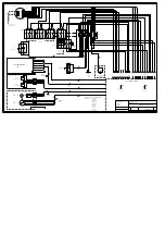
POWER SUPPLY: +5V,+12V AND +32V

+5V/1Amp

X18:

KEYBOARD

TASTATUR

A1P

(EPROM)

80000-BFFFF

(MAX199B)

SELECT LOGIC I

R/W LOGIC

CPU

40000-7FFFF

00000-3FFFF

(82C55)

(SRAM)

C0000-FFFFF

MEMORY

DISPLAY INTERFACE

0-3V

X7-1

FL INVERTER

DELAY 50ns

3x4K7

1,50V

(LIGHT ON\)

-15V

÷(6V-10V)

256 x 8 BIT

NVRAM

OR 128K x 8-BIT EPROM

SRAM

EPROM

0,96V

0V

PERIPHERAL INTERFACE

200-300m S

RESET GENERATOR

RESET PULS:

VCC

GND

ENCODERS

ROTARY OPTICAL

CHB

CHA

TXD0

GND

SERVICE

X16:

COM.

+5V

RXD0

KEYBOARD BUZZER:

X10:

CURRENT FROM
CUTTING
MOTOR

I - TRANS

SOURCE GND-A

Vin = 2,46V

Vac = 3,03V peak

A/D CONVERTER:

CONTROL INPUT FOR ARM POS.

24V AC.

9,5V AC.

12V AC.

CCFL-tube

360VRMS @ 5mA

Connector type
Header RM 3

X17:

3x1K

X7-2

Pin 17

Pin 21

Pin 22

Pin 23

CUT-MOTOR CURRENT:

POWER ON

ANALOG TO DIGITAL INPUT:

4,096V

4,096V

IN 5

IN 7

GND-A

IN 6

2 MAR. 99 / DEM

A[0..19]

A[0..17]

A[0..16]

A[0..17]

ADD
CH6

ADD
CH5

ADD
CH7

MAX199B CNI

MAX199B CNI

MAX199B CNI

N15

N15

ADD
CH1

MAX199BC NI

N15

ADD
CH0

MAX199B CNI

N15

Pin 16

N15

POWER SUPPLY DECOUPLING:

X14:

N.C.

UNITOM - 5, - 50:

X1:

Rev.: A Change R48 150K -> 120K,
R49 200K -> 180K: (24-09-01 DEM)
Rev.: B Change R48 120K -> 200K,
R49 180K -> 150K: 30-01-04 KFC)
Rev.: C (FTH 10-08-2004)
R77+R80 changed from 1k to 150R

Phone +45 3670 35 00

C

Struers A/S

15313200

Tuesday, August 10, 2004

1

2

Valhoejs Alle 176

DK 2610 Roedovre

Denmark

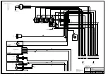
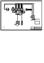
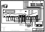
Circuit Diagram

EK

Size

Scale

CAGE Code

DWG NO

Rev

Sheet

of

PT[0..5]

PT[0..5]

PT[0..5]

PT[0..5]

P2[0..5]

D[0..7]

D[0..7]

PA[0..7]

PC[0..1]

PC[4..6]

D[0..7]

D[0..7]

D[0..7]

D[0..7]

D[0..7]

P2[0..5]

PB[2..5]

+12V

+12V

0V

0V

PT3

PT1

PT0

A19

PT1

MEMRD\

P07

RESET\

P17

CS3

RD/WR\

A18

TXD0

A18

PT3

P14

CS0

P16

P06

CS1

P13

CS2

PT2

MEMW R\

PT5

A19

RXD0

PT4

P15

PT0

PT6
PT7

IOSTB\

A0

IOSTB\

-15V

P23

RD/WR\

RVERS

-15V

VEE

C/D

6X8

LCDWR\

V0

P12

RESET

P06

P07

CS3

MEMRD\

CS0

MEMW R\

LCDCE\

LCDRD\

PT5

LCDRD\

A1

MEMRD\

RESET

A0

PA2

PA3

PA5

PA4

PC1

CS1

PA6

MEMW R\

PA0

PA7

PA1

PC0

D5

MEMRD\

A8

A1

A10

A3

A2

A8

A0

A2

A15

A13

A0

A2

A6

A5

A0

A10

A9

A7

A14

A4

A12

A3

A17

A1

A10

A4

A9

A14

A14

A11

A12

A16

A7

A5

A7

A3

A13

A15

A11

A11

A6

A13

A16

A1

A4

A9

A6

A15

A16

A17

A12

A8

A5

PT4

RESET

P13

D2

D2

D1

D7

D2

D4

D4

D4

D7

D5

D6

D3

D3

D7

D2

D3

D0

D0

D0

D6

D5

D5

D1

D1

D6

D3

D0

D4

D7

D6

D6

D7

D1

D0

D5

D4

D3

D1

D2

RXD0

TXD0

P27

ADD0

CS2

MEMW R\

MEMRD\

P26

D7

D6

D5

D4

D1

D0

D2

D3

V0

LCDWR\

LCDRD\

LCDCE\

C/D

RESET\

DB2

DB6

DB1

DB7

DB4

DB0

DB5

DB3

++5V

RVERS

LCDRD\

V0

LCDCE\

DON

C/D

LCDWR\

6X8

RESET\

VEE

DB7

DB3

DB1

DB2

DB0

DB6

DB5

DB4

PC7

DON

++GND

++5V

++GND

REF

REF

P12

ADD5

ADD6

REF

ADD7

P17

P16

P27

P26

PT2

ADD0

ADD1

ADD5

ADD6

ADD7

ADD1

PB5

PB3

PB2

PB4

DB0

DB1

DB2

DB3

DB4

DB5

DB6

DB7

PC7

RESET\

P23

P22

P24

P24

P25

P22

P25

P2[0..5]

P20

P24

P25

P21

P2[0..5]

P20

P23

P21

DB[0..7]

DB[0..7]

DB[0..7]

PC5

PC4

PC6

P03

P02

P05

P01

P04

P00

P0[0..5]

PT6

PT7

ADD2

ADD3

ADD4

P14
P15

RESET\

REF

N24

+24V

+12V

24AC

+5V

GND-P

GND

+5V

VCC

GND

+5V

GND

GND

GND

+5V

+5V

+5V

GND

GND

GND

+5V

+5V

GND

GND

GND

GND

++12V

GND

GND

+5V

GND

+5V

GND

+5V

GND-A

GND-A

GND

+5V

++12V

++12V

GND-A

GND-A

GND-A

+5V

GND-A GND

GND-A

GND

GND

+5V

GND-A

+5V

GND-S

GND-S

GND-S

GND-S

GND-S

GND-S

GND-S

GND-S

GND-A

GND-A

GND-A

GND

GND-S

GND-S

GND-S

GND-S

+24V

GND-P

GND-S

GND-S

+12V

+12V

GND-S

GND-A

GND-A

GND-A

GND-A

GND-A

GND-A

GND-S

GND-S

GND-S

GND-S

GND-A

+5V

+5V

+5V

+5V

+5V

+5V

+5V

+5V

+5V

+5V

GND

GND

GND

GND

GND

GND

GND

GND

GND

GND

GND

GND

GND

GND

GND-S

V10

1N4148

2x10 POL HEADER

X701

1

2

3

4

5

6

7

8

9

10

11

12

13

14

15

16

17

18

19

20

C9

100nF/63V

6

R57

4K75 1%

C5

100nF/63V

C92

10uF/50V

V16

ZTX1055A

C58

100nF/50V

1

D1A

74HCT32

1

2

3

R58

1K0 1%

C8

100nF/63V

5

CL39

DSS306

C4

100nF/63V

CL40

DSS306

C2

100nF/63V

XS3

44 PIN PLCC SOCKET

C10

1m2F/16V

Low ESR

N12

MAX766

6

7

5

1

8

2

4

3

V+

V+

GND

OUT

LX

FB

REF

SHDN

+

C1

2200µF/25V

TYPE KME

RN9A

4x10K SIL SEP

1

2

V8

BYV10-30

+

C6

120µF/50V

Low ESR

&

D2D

74HCT13 2

12

13

11

+

C7

4700uF/35V

TYPE KME

C76
100pF/100V

RN4A

1

2

+

C11

470uF/50V

TYPE KME

+

C53

100uF/40V

Low ESR

V2

BYV28-150

+

C54

100uF/40V

Low ESR

FV2

ICTE-36

R48

200k

C59

100nF/50V

FV4

SA-5.0

R66

150R

R47

1K0

FV3

ICTE-36

FV1

ICTE-18

R49

150k

CL1

DSS306

CL2

DSS306

C81

10nF/63V

+

C78

4µ7F/50V

CL28

DSS306

R63

4K99 1%

Tpuls

TEST1

45-50mS

R74
0R0

C75

&

D2A

74HCT13 2

1

2

3

CL3

DSS306

L1

2x10mH/1A

R72

N.C.

C69

N13

MAX515

2

1

3

6

8

7

4

5

SCLK

DIN

CS

REFIN

VDD

OUT

DOUT

GND

C57

V15
BAT48

HV1

RED LED

R65

4K99 1%

C83

10nF/63V

C89

C93

27pF/2kV

R1
680R

STJ3

C88

+

C96

10uF/50V

R2

5K6

R64

4K99 1%

3EN1

3EN2

G3

2

1

D3

74HCT2 45

1

19

2

3

4

5

6

7

8

9

18

17

16

15

14

13

12

11

C55

100pF/100V

HL3

C82

10nF/63V

N16

X2402I

1

2

3

6

7

5

A0

A1

A2

SCL

TEST

SDA

HL1

GREEN

R67

4K99 1%

CL45

DSS306

CL50

DSS30 6

RN11E

6x4K7 SIL BUS

1

6

+

C95
100uF/10V

V17

ZTX1055A

HL4

CL47

DSS306

RN11C

6x4K7 SIL BUS

1

4

+

C97

10uF/50V

HL5

CL46

DSS306

V14
BAT48

HL2

CL44

DSS306

HV2

RED LED

+

C79

4µ7F/50V

HL6

R26

330R

STJ2

R69

N.C.

R50

200K

R25

330R

C23

100nF/63V

L3

10uH/0,41A

R82

2K2

L6

10µH

R70
150R

STJ1

D.E.M.

R56
NC.

C80

100nF/50V

L5

47µH/1,3A

RN11B

6x4K7 SIL BUS

1

3

RN9B

4x10K SIL SEP

3

4

3

4

N17

TLC7705I

3

7

2

1

6

5

CT

SENSE

RESIN

REF

RESET

RESET

3

4

R87

4K7

1

D1B

74HCT32

4

5

6

RN15F

6x4K7 SIL BUS

1

7

TP3

\RESET

2

R86

0R0

C52

100nF/50V

3

RN11A

6x4K7 SIL BUS

1

2

L8

220uH/0.6A

3

4

C94

100nF/100V

RN14C

3x10K SIL SEP

5

6

R85

N.C.

9

10

&

D2C

74HCT13 2

9

10

8

1

5

R81

2K2

5

6

V9

BAT48

1

1

6

C77

10nF/50V

1

4

5

6

7

RN3A

1

2

1

2

3

4

C85

10uF/50V

6

R71

0R0

5

3

1

D1D

74HCT32

12

13

11

CL27

DSS306

1

3

R76

560R

R73

N.C.

RN13A

3x10K SIL SEP

1

2

1

D7B

74HCT1 4

3

4

8

2

C68

100nF/63V

4

1

1

R68

0R0

R83

1K0

C84

4u7F/50V

R84

1K0

1

D7A

74HCT1 4

1

2

5

6

C87

15p

R75

560R

4

1

2

0

1

G -0

3

DX

0

1
2

3

D10B

74HCT1 39

12

11

10

9

14

13

15

HV9

RED LED

STIK 2 POL

2

G1

16MHz

HV8

RED LED

L4

10uH/0,41A

0

1 G -

0
3

DX

0

1
2

3

D10A

74HCT1 39

4

5

6

7

2

3

1

CL51

DSS30 6

C86

15p

CL49

DSS30 6

RN9C

4x10K SIL SEP

5

6

XS1

84 POL PLCC SOCKET

RN11D

6x4K7 SIL BUS

1

5

CL52

DSS30 6

C72

4u7F/50V

D11

70320L-10 V25

21

22

23

24

25

26

27

28

29

30

31

32

33

34

35

36

37

38

39

40

13

14

15

16

17

18

19

20

83

84

1

2

48

51

52

54

55

56

57

58

76

67

68

69

70

71

72

73

74

4

5

6

7

8

10

11

12

41

44

43

45

47

46

78

79

81

82

59

60

61

62

63

64

65

66

9

49

53

75

3

A0

A1

A2

A3

A4

A5

A6

A7

A8

A9

A10

A11

A12

A13

A14

A15

A16

A17

A18

A19

D0

D1

D2

D3

D4

D5

D6

D7

RD/WR

MSTB

IOSTB

MREQ

P20/DRQ0

P21/DACK0

P22/TC0

P23/DRQ1

P24/DACK1

P25/TC1

P26/HOLDAK

P27/HLDRQ

VTH

PT0

PT1

PT2

PT3

PT4

PT5

PT6

PT7

P00

P01

P02

P03

P04

P05

P06

P07/CLKOUT

RXD0

TXD0

CTS0

RXD1

TXD1

CTS1

X1

X2

RESET

REFRQ

NMI

P11/INTP0

P12/INTP1

P13/INTP2/INTAK

P14/INTR/POLL

P15/TOUT

P16/SCK0

P17/READY

IC

IC

IC

IC

EA/VPP

2

1

HA1

SM-21L

5

N11A

2803A

1

9

10

18

6

R35

4K7

C60

3

D6

MSM82C55 A-2VJS

38

37

36

35

33

32

31

30

6

40

10

9

39

7

5

4

3

2

44

43

42

41

20

21

22

24

25

26

27

28

16

17

18

19

15

14

13

11

D0

D1

D2

D3

D4

D5

D6

D7

RD

WR

A0

A1

RESET

CS

PA0

PA1

PA2

PA3

PA4

PA5

PA6

PA7

PB0

PB1

PB2

PB3

PB4

PB5

PB6

PB7

PC0

PC1

PC2

PC3

PC4

PC5

PC6

PC7

4

CL48

DSS306

1

C47

C56

RN9D

4x10K SIL SEP

7

8

C70

L7

10µH

2

F1

1,6Amp

L2

400uH/1A

N14

TL081CP

2

3

4

6

7

&

D2B

74HCT1 32

4

5

6

F2

3,15Amp

RV1

S10K35

3

1

D1C

74HCT32

9

10

8

RV3

S10K35

RV2

S10K35

2x10 POL HEADER

X702

1

2

3

4

5

6

7

8

9

10

11

12

13

14

15

16

17

18

19

20

D9

256K X 8-BIT EPR OM

12

11

10

9

8

7

6

5

27

26

23

25

4

28

29

3

2

22

24

1

31

13

14

15

17

18

19

20

21

32

16

30

A0

A1

A2

A3

A4

A5

A6

A7

A8

A9

A10

A11

A12

A13

A14

A15

A16

CE

OE

VPP

PGM

O0

O1

O2

O3

O4

O5

O6

O7

VCC

GND

A17

F3

3,15Amp

2

XS2

32-PIN IC-SOCKET

C98

R60

24K9 2%

3

D8

128K X 8-BIT SRA M

12

11

10

9

8

7

6

5

27

26

23

25

4

28

3

31

2

22

30

24

29

13

14

15

17

18

19

20

21

32

16

1

A0

A1

A2

A3

A4

A5

A6

A7

A8

A9

A10

A11

A12

A13

A14

A15

A16

CS1

CS2

OE

WE

D0

D1

D2

D3

D4

D5

D6

D7

VCC

GND

NC

IN

GND

ON

FB

O

N1

LM257 5T-5.0

4

2

5

3

1

2

HEADER 4 POL

1

4

V11

BAT48

-

+

V1

BL2-04

4

R59

8K2

-

+

V3

BU6-08

N15
MAX199

14

13

12

11

10

7

8

9

2

3

4

5

6

1

26

25

16

17

18

19

20

21

22

23

24

28

15

27

D0/D8

D1/D9

D2/D10

D3/D11

D4

D7

D6

D5

CS

WR

RD

HBEN

SHDN

CLK

REF

REFADJ

CH0

CH1

CH2

CH3

CH4

CH5

CH6

CH7

INT

DGND

AGND

VDD

RN11F

6x4K7 SIL BUS

1

7

T1

CTX110092-2

4

3

2

5

1

7

9

1

C3

100nF/63V

PB[2..5]

PC[0..1]

PC[4..6]

PA[0..7]

P0[0..5]

Содержание Unitom-5

Страница 1: ...Manual No 15337001 Date of Release 15 11 2005 Unitom 5 Instruction Manual...

Страница 2: ...onnection with Struers equipment covered by the Instruction Manual Service Manuals Struers Service Manual may only be used by a trained technician authorised by Struers The Service Manual may only be...

Страница 3: ...Do not touch anything inside the cutting chamber while positioning the cut off wheel with the position button 7 Struers recommends the use of exhaustion as the materials to be cut may emit harmful ga...

Страница 4: ......

Страница 5: ...g the Controls 8 Front Panel Controls of Unitom 5 8 Groups of Keys 8 Acoustic Signals 8 Front Panel Controls 9 Cooling Valve Positions 10 Reading the Display 11 Reading the Display during the Cutting...

Страница 6: ...truers table LABUL or a table which is able to carry a weight of min 200 kg Adjust the table height using the screws in the table legs It is important that the table and Unitom 5 are level Place Unito...

Страница 7: ...f the Unitom 5 components c Front panel controls d Cutting Table e Quick clamping device f Table LABUL optional g Recirculation cooling unit h Removable plate Can be replaced by a rubber curtain optio...

Страница 8: ...wn Earth Yellow green L1 Black L2 Red L3 Orange Earth Green Check that the cut off wheel rotates in the direction indicated on the label attached to the guard of Unitom 5 If the direction of rotation...

Страница 9: ...s Wasser in den Tank der Umlaufk hlung flie en kann F hren Sie den R cklaufschlauch durch die ffnung auf der R ckseite des Tischs Stellen Sie den Tank auf den Rollwagen Legen Sie einen wegwerfbaren Pl...

Страница 10: ...ly Afterwards the display will change to the screen for cutting ESC Press ESC to come to the MAIN MENU D The MAIN MENU is the highest level in the menu structure From here you can go to cutting or to...

Страница 11: ...ress MENU UP DOWN mON to select Language D e Press ENTER e to activate the Language pop up menu D mO mN Press MENU UP DOWN mON to select the language you prefer D e Press ENTER e to accept the languag...

Страница 12: ...sed indicates that the command has been accepted A long beep indicates that the key is inactive at the moment Three long beeps indicate that the cutting process is finished Using the Controls Front Pa...

Страница 13: ...screens f STOP o Stops the cutting process l FUNCTION KEY F2 Controls for various purposes See the bottom of the individual screens gh POSITION v V Moves the cut off wheel up or down Keep the key pre...

Страница 14: ...to the left Turn the knob counter clockwise to vertical position for cooling of cut off wheel Turn the knob to regulate the flow while flushing the cutting chamber Turn the knob clockwise to vertical...

Страница 15: ...ea The cutting motor can only be intermit tently loaded The built in thermo fuse might shut off the cutting motor Wheel Position The actual position of the cut off wheel counted from the top position...

Страница 16: ...ng D e Press ENTER e to edit the value D Two square brackets appear around the value mO mN Press MENU UP DOWN mON to increase or decrease the numeric value D e Press ENTER e to accept the new value Pr...

Страница 17: ...to change D e Press ENTER e to edit the value D A pop up menu appears D mO mN Press MENU UP DOWN mON to select the correct value D e Press ENTER e to accept the new value and to return to the previou...

Страница 18: ...ing device with the locking handle After clamping you may lower the cut off wheel to a position at least 1 mm above the workpiece to test the correct position of the cut on the workpiece Press POSITIO...

Страница 19: ...alue D Two square brackets appear around the value mO mN Press MENU UP DOWN mON to increase or decrease the numeric value D e Press ENTER e to accept the new value Pressing Esc aborts the changes pres...

Страница 20: ...start and the cut off wheel physically touching the workpiece Press the function key F1 The cut off wheel moves down fast until it touches the workpiece From that minute Unitom 5 automatically changes...

Страница 21: ...ops rotating and the cooling water stops To be used if you want to stop the cutting at a certain depth please see Advanced Operations for further information You can always stop the cutting process by...

Страница 22: ...protection guard open to let the cutting chamber dry completely AVOID RUST Leave the protection guard open to let the cutting chamber dry completely Flushing the Cutting Chamber NB Do not clean the pr...

Страница 23: ...r Workpieces 23 Using the Continue Function 23 Opening the Protection Guard before using the Continue Function 23 Using Autostop 24 Using Fixed Stop 25 Using Fixed Stop together with Autostop 25 Setti...

Страница 24: ...rvice 36 Replacing the Cooling Water 36 Lubrication of Bearings for Tilting Frame 37 Maintenance of Cutting Tables 38 Maintenance of Cut off Wheels 38 Storing of Bakelite Bonded Al2O3 Cut off Wheels 3...

Страница 25: ...5 Instruction Manual 21 1 Advanced Operations Press Esc until you reach the Main Menu D mN Press MENU DOWN mN to select CONFIGURATION D e Press ENTER e to activate the CONFIGURATION menu D Configurati...

Страница 26: ...ally retracts the cut off wheel to the top position Start Unitom 5 automatically retracts the cut off wheel to the original position of the cut off wheel at the time you pressed START s Stay The cut o...

Страница 27: ...workpiece so that the wheel will cut the smallest possible cross section If the cutting is temporarily stopped by pressing STOP o during cutting the cut off wheel moves up to the position from which y...

Страница 28: ...n is set to MAX Press F4 When cutting pipes or other workpieces with changing cross sections the cut off wheel may retract before the workpiece has been cut It can then be necessary to switch Autostop...

Страница 29: ...only Clamp the workpiece so that you can move the cut off wheel along the workpiece Press POSITION DOWN V to move the cut off wheel down along the workpiece to the desired stop position Remember to ta...

Страница 30: ...the reduced Feed Speed and reduces the Feed Speed repeatedly if necessary Next time the same type of sample has to be cut the reduced value for Feed Speed can be used After the Feed Reduction Feature...

Страница 31: ...burrs Use a softer cut off wheel Clamp the workpiece securely at the right hand clamping device Tighten the left hand clamping device just enough to prevent the workpiece to shifting on being cut How...

Страница 32: ...chine Please check in advance with your local authorities if this type of protection is approved in your country Remove the 6 nuts holding the plastic side plate and splice plate on the protection gua...

Страница 33: ...0 mm T slots Additional table for support of large workpieces With exchangeable stainless steel bands 140 x 315 mm 5 5 x 12 4 For Exotom and Unitom machines UNIFT Replacement Stainless Steel Bands For...

Страница 34: ...for collecting waste material in the recirculation cooling unit Package with 10 pcs EXOSP Cut off Wheel IMPORTANT The max rotational speed of Unitom 5 is 2775 rpm when running idle The Struers EXO ra...

Страница 35: ...The desired cutting operation cannot start before the guard has been closed Close the guard and try again No cooling The cooling valve is not in cooling position Check cooling valve setting Display is...

Страница 36: ...Insufficient cleaning Clean with mild soapy water do not use the cleaning hose The protection guard will not open The safety lock has stuck Open the lock with a thin flat screw driver Clean and lubri...

Страница 37: ...ly Incorrect clamping of the workpiece Make sure that only one of the quick clamping devices is tight The other device should only press lightly Use support tools if the geometry of the workpiece make...

Страница 38: ...p position is set too low See Section Basic Operation Stopping the cutting The workpiece breaks when clamped The workpiece is brittle Place the workpiece between two polystyrene plates NB Always cut b...

Страница 39: ...oling water Remember to add Struers Additive for Cooling Fluid One part of Additive for 33 parts of water Use a refractometer to check the concentration of additive Concentration Brix value The concen...

Страница 40: ...2 Monthly Service Replacing the Cooling Water Please Note Too high a level of coolant in the tank might damage the pump To avoid this place the disposable container so that the pre punched hole is in...

Страница 41: ...ite circle in the photo Lubricate in the two grease nipples with the grease gun and move the spindle cutting motor up and down by hand until grease comes out at the shaft Use water repelling grease e...

Страница 42: ...heavy mechanical load or heat Store the cut off wheel in a dry place horizontally on a plane support preferably under light pressure A clean and dry cut off wheel does not corrode Therefore clean and...

Страница 43: ...25 11 8x0 08x1 25 Cutting Chamber Geometry Max workpiece dimensions Thickness Width Length Max cutting capacity Max cutting thickness Max length of cut with a sample thickness of The max cutting capac...

Страница 44: ...el IEC 204 1 EN 60204 1 VDE 0113 89 392 EEC 89 339 EEC Max admissible unbalance Uper according to ISO 1940 1 Balance Quality Grade G6 03 Uper 2 gmm kg 110 gmm Approx 76dB A during cutting at a distanc...

Страница 45: ...41 7 Menu Overview Main Menu Cutting Configuration Feed Display Contrast s vV Position stop Language Cutting Unit Feed o Autostop Fast Down Return Position Position Stop Feed Reduction Cutting Feed s...

Страница 46: ...eel stops rotating and the cooling water stops The feed speed can be set before the cutting and changed during the cutting Press ENTER e to edit the value Press MENU UP DOWN mON to change the value Pr...

Страница 47: ...Unitom 5 Gebrauchsanweisung Handbuch Nr 15337001 Auslieferungsdatum 15 11 2005...

Страница 48: ...her Ein von der Firma Struers ver ffentlichtes Wartungshandbuch darf nur von ausgebildeten Technikern benutzt werden die von Struers dazu berechtigt wurden Das Wartungshandbuch darf nur in Zusammenhan...

Страница 49: ...hlt den Gebrauch einer Absaugvorrichtung weil beim Trennen gef hrliche Gase oder Trennr ckst nde entstehen k nnen Beachten Sie bitte die Gebrauchsanweisung der Trennscheiben Falls Sie f r das Trennen...

Страница 50: ......

Страница 51: ...feld von Unitom 5 8 Tastengruppen 8 Akustische Signale 8 Elemente des Bedienfeldes 9 Stellungen des K hlventils 10 Anzeige ablesen 11 Anzeige w hrend des Trenn vorgangs ablesen 11 Ruhemodus 11 Werte P...

Страница 52: ...rden oder auf einem Tisch der ein Gewicht von mindestens 200 kg tragen kann Stellen Sie die Tischh he mit den Stellschrauben der Tischbeine ein Tisch und Unitom 5 m ssen unbedingt horizontal stehen St...

Страница 53: ...Namen der Teile des Unitom 5 kennenzulernen c Bedienungsfeld d Trenntisch e Schnellspannvorrichtung f Tisch LABUL Zubeh r g Umlaufk hlung h Abnehmbare Deckplatte Kann durch Gummisch rze ersetzt werden...

Страница 54: ...gr n L1 Schwarz L2 Rot L3 Orange Erde Gr n Pr fen Sie ob die Trennscheibe in die Richtung dreht die das Schild auf der Innenseite der Schutzhaube zeigt Wenn dies nicht der Fall ist 50 hz 60 hz Vertaus...

Страница 55: ...s Wasser in den Tank der Umlaufk hlung flie en kann F hren Sie den R cklaufschlauch durch die ffnung auf der R ckseite des Tischs Stellen Sie den Tank auf den Rollwagen Legen Sie einen wegwerfbaren Pl...

Страница 56: ...anach wechselt die Anzeige zum Men TRENNEN ESC Durch Dr cken der Taste ESC gelangen Sie ins HAUPTMEN D Das HAUPTMEN steht an der Spitze der Men struktur Von hieraus gelangen Sie in die Men s KONFIGURA...

Страница 57: ...ste MEN AUF AB mON w hlen Sie die Sprache aus D e Mit der Taste EINGABE e rufen Sie das Einblendmen der Sprache auf D mO mN Mit der Taste MEN AUF AB mON w hlen Sie Deutsch aus D e Mit der Taste EINGAB...

Страница 58: ...zeigt an da die Eingabe best tigt ist Ein langer Ton zeigt an da diese Funktion derzeit nicht zur Verf gung steht Mit drei langen T nen wird das Ende des Trennvorgangs angek ndigt Gebrauch der Bedien...

Страница 59: ...Unterschiedliche Verwendung Die jeweils zutreffende Funktionsweise steht in der untersten Zeile des Men s gh POSITION AUF AB v V Bewegt die Trennscheibe auf ab Anhaltendes Dr cken bewegt die Trennsche...

Страница 60: ...Knopf im Gegen uhrzeigersinn so da der Griff senkrecht steht Beim Reinigen der Trennkammer regulieren Sie den K hlmittelflu durch Drehen des Knopfs Beim Reinigen der Trennkammer stellen Sie den K hlm...

Страница 61: ...ieb benutzt werden Die eingebaute thermische Sicherung k nnte den Trennmotor jederzeit abschalten Scheibenposition Derzeitige Position der Trennscheibe gez hlt von der h chstgelegenen Lage der Trennsc...

Страница 62: ...ameter ge ndert werden soll Daraufhin erscheinen zwei eckige Klammern um diesen Wert mO mN D Mit den Tasten MEN AUF AB mON erh hen bzw erniedrigen Sie den Wert dieses numerischen Wertes e Mit der Tast...

Страница 63: ...rkierte Wert ge ndert werden soll Dadurch wird ein Einblendmen aufgerufen D mO mN D Mit den Tasten MEN AUF AB mON w hlen Sie die gew nschte Einstellung aus e Mit der Taste EINGABE e best tigen Sie die...

Страница 64: ...die Probe und arretieren Sie die Schnellspannvorrichtung mit dem Verriegelungsgriff Nach dem Einspannen fahren Sie die Trennscheibe bis mindestens 1 mm ber die Probe dadurch k nnen Sie die Schnittlage...

Страница 65: ...zwei eckige Klammern um diesen Wert mO mN D Mit den Tasten MEN AUF AB mON erh hen bzw erniedrigen Sie den Betrag dieses numerischen Wertes e Mit der Taste EINGABE e best tigen Sie den neuen Wert Mit...

Страница 66: ...e die Taste F1 Die Trennscheibe f hrt mit erh hter Geschwindigkeit so weit nach unten bis sie das Werkst ck ber hrt In diesem Augenblick stellt Unitom 5 die Vorschubgeschwindigkeit automatisch wieder...

Страница 67: ...lichkeit benutzen Sie wenn die Trennung in einer bestimmten Schnitt bzw Trenn tiefe gestoppt werden soll genaue Ausf hrungen hierzu finden Sie im Kapitel Details und Besonderheiten der Bedienung Sie k...

Страница 68: ...ermeiden Sie Rostentwicklung Lassen Sie die Schutzhaube ge ffnet so da die Trennkammer v llig austrocknet Trennkammer sp len HINWEIS Reinigen Sie die Schutzhaube nicht mit dem Reinigungsschlauch sonde...

Страница 69: ...annen 23 Die WEITER Funktion benutzen 23 Schutzhaube ffnen vor Bet tigung der WEITER Funktion 23 Auto Stopp verwenden 24 Programmierung einer festen Stopp Position 25 Feste Stopp Position zusammen mit...

Страница 70: ...onatliche Pflege 36 K hlwasser ersetzen 36 Schmieren der Lager des Kipprahmens 37 Wartung der Trenntische 38 Wartung der Trennscheiben 38 Aufbewahren von bakelit gebundenen Al2 O3 Trennscheiben 38 Pfl...

Страница 71: ...nd Besonderheiten der Bedienung Dr cken Sie so oft die Taste Esc bis das HAUPTMEN erscheint D mN Mit der Taste MEN AB mN w hlen Sie das Men KONFIGURATION aus D e Mit der Taste EINGABE e rufen Sie das...

Страница 72: ...ennscheibe automatisch in die Position zur ck die sie im Augenblick des Dr ckens der Taste START s eingenommen hatte Bleibe Die Trennscheibe verharrt unten Verwenden Sie diese Einstellm glichkeit f r...

Страница 73: ...so ausgerichtet ist da der kleinstm gliche Querschnitt abgetrennt wird Wenn der Trennvorgang vor bergehend durch Dr cken der Taste STOP o unterbrochen wurde f hrt die Trenn scheibe in die Ausgangslag...

Страница 74: ...cken von F4 stellen Sie ihn auf MAX ein Werden beispielsweise Rohre oder andere Werkst cke mit wechselhaften Querschnitten getrennt kann sich die Trennscheibe bereits zur ckziehen noch bevor die Prob...

Страница 75: ...da Sie die Trennscheibe neben der Probe nach unten entlangfahren k nnen Mit der Taste POSITION AB V bewegen Sie die Trenn scheibe neben der Probe entlang so weit nach unten bis die gew nschte Stopp Po...

Страница 76: ...uziert sie je nach Erfordernissen in weiteren Schritten Wenn der gleiche Materialtyp nochmals zu trennen ist kann die reduzierte Vorschubgeschwindigkeit verwendet werden Falls zuvor eine Reduzierung d...

Страница 77: ...nscheibe Spannen Sie die Probe fest in die auf der rechten Seite liegende Spann vorrichtung ein Ziehen Sie die linke Spannvorrichtung nur gerade so weit fest da die Probe beim Trennen nicht verrutsche...

Страница 78: ...t tritt am wenigsten Spritzwasser nach au en Kl ren Sie im Voraus mit den rtlichen Sicherheits beh rden ob solche Schutzvorrichtungen in Ihrem Land zugelassen sind Entfernen Sie die 6 Schrauben mit de...

Страница 79: ...Zus tzlicher Trenntisch zur Unterst tzung von gro en Proben Mit auswechselbaren Stahlschienen 140 x 315 mm F r Exotom und Unitom Maschinen UNIFT Rostfreie Stahlschienen als Ersatz F r den automatisch...

Страница 80: ...us der Umlaufk hlung Packung mit 10 Stk EXOSP Trennscheibe Hinweis In einigen L ndern mu bei der Verwendung einer 350 mm Trennscheibe ein Flansch von min 119 mm UNIFL benutzt werden WICHTIG Die max Dr...

Страница 81: ...ossen wurde Schlie en Sie die Schutzhaube und starten Sie erneut Keine K hlung Das K hlventil steht nicht in der Stellung K hlen Pr fen Sie die Stellung des K hlventils nach LCD Anzeige zeigt nichts a...

Страница 82: ...ng ungen gend Reinigen sie mit einer milden Seifenwasserl sung verwenden Sie dazu nicht den Reinigungs schlauch Die Schutzhaube l t sich nicht ffnen Die Sicherheitsverriegelung ist blockiert ffnen Sie...

Страница 83: ...zogen sein Probe nicht richtig eingespannt Vergewissern Sie sich da nur eine der beiden Schnellspann vorrichtungen hart angezogen ist Die andere Vorrichtung sollte nur leichten Druck aus ben Benutzen...

Страница 84: ...z ge der Bedienung Trennen stoppen Probe bricht beim Einspannen Probe ist spr de Legen Sie die Probe zwischen zwei Styroporstreifen HINWEIS Trennen Sie spr de Proben immer mit gr ter Vorsicht Probe is...

Страница 85: ...werden Denken Sie daran Struers Additiv f r K hlwasser zuzusetzen ein Teil Additiv auf 33 Teile Wasser Die Konzentration des Additivs wird mit Hilfe eines Refraktometers gemessen Konzentration Brix E...

Страница 86: ...2 Fig 1 Fig 2 Monatliche Pflege K hlwasser ersetzen Beachten Sie bitte Falls der K hlmittelstand im Tank zu hoch ist k nnte die Pumpe Schaden nehmen Dies k nnen Sie vermeiden Legen Sie den wegwerfbar...

Страница 87: ...s gekenn zeichnet Schmieren Sie beide Nippel mit der Fettspritze ab Bewegen Sie die Welle bzw den Trennmotor so lange von Hand auf und ab bis Fett am Wellenschaft austritt Verwenden Sie dazu ein wasse...

Страница 88: ...g sind strikt zu vermeiden Die Trennscheiben sind an einem trockenen Aufbewahrungsort auf horizontaler Unterlage m glichst noch leicht beschwert zu lagern Saubere und trockene Trennscheiben sind ohne...

Страница 89: ...8 x 0 1 x 1 25 11 8 x 0 08 x 1 25 Abmessungen der Trennkammer Max Probenabmessungen Dicke Breite L nge Max Trennkapazit t Max Trenndicke Max Trennl nge bei einer Probendicke von Unter Umst nden kann...

Страница 90: ...IEC 204 1 EN 60204 1 VDE 0113 89 392 EEC 89 339 EEC Max zul ssige Unwucht Uper gem ISO 1940 1 Unwucht Qualit tsklasse G6 03 Uper 2 gmm kg 110 gmm Etwa 76dB A beim Trennen gemessen in einer Entfernung...

Страница 91: ...sicht HAUPTMEN Trennen Konfiguration Vorschub Anzeigenkontrast s vV Stopp Position Sprache Trennen Einheit Vorschub o Auto Stopp Schnellabsenken R ckkehrposition Stopp Position Vorschub reduktion Tren...

Страница 92: ...er auch w hrend der Trennung zu ver ndern Mit EINGABE e wird ein Wert zur nderung freigegeben Mit MEN AUF AB mON wird der Wert ge ndert Mit EINGABE e wird der ge nderte Wert best tigt Schutzhaube ffne...

Страница 93: ...Unitom 5 Mode d emploi Mode d emploi no 15337001 Date de parution 15 11 2005...

Страница 94: ...utilis que pour l quipement Struers pour lequel il a t sp cifiquement r dig Manuels de maintenance Un manuel de service de Struers ne peut tre utilis que par un technicien sp cialiste autoris par Str...

Страница 95: ...ron onnage lors du positionnement de la meule de tron onnage l aide des touches de positionnement 7 Struers recommande l utilisation d un syst me d aspiration car les mat riaux tron onner peuvent d ga...

Страница 96: ......

Страница 97: ...es de touches 8 Signaux sonores 8 Touches de contr le sur le panneau frontal 9 Positions de la soupape de refroidissement 10 Lire l affichage 11 Lire l affichage pendant le processus de tron onnage 11...

Страница 98: ...onnelle Struers LABUL ou sur une table capable de porter un poids d au min 200 kg R gler la hauteur de la table l aide des vis plac es dans les pieds de la table Il est important que la table et Unito...

Страница 99: ...Touches du panneau frontal d Table de tron onnage e Dispositif de serrage rapide f Table LABUL optionnelle g Unit de recyclage h Plaque amovible Peut tre remplac e par un rideau de caoutchouc optionn...

Страница 100: ...ir L2 Rouge L3 Orange Terre Vert V rifier que la meule de tron onnage tourne dans le sens indiqu sur l tiquette attach e l cran d Unitom 2 Si le sens de rotation n est pas correct 50 hz 60 hz Interver...

Страница 101: ...r que l eau soit dirig e dans le r servoir de recyclage Guider le tuyau d coulement travers l ouverture au dos de la table Placer le r servoir sur le wagonnet Placer un sac plastique jetable EXOSP com...

Страница 102: ...i du tron onnage ESC Appuyer sur ESC pour passer au MENU PRINCIPAL D Le MENU PRINCIPAL est le niveau le plus lev dans la structure de menu A partir de l il est possible de passer au menu du tron onnag...

Страница 103: ...S LE HAUT LE BAS mON pour choisir la langue D e Appuyer sur ENTER e pour activer la langue dans le menu d roulant D mO mN Appuyer sur MENU VERS LE HAUT LE BAS mON pour choisir le fran ais D e Appuyer...

Страница 104: ...ndique que la commande a t accept e Un bip long indique que la touche est inactive pour le moment Trois bips longs indiquent que le processus de tron onnage est achev Utilisation des touches de contr...

Страница 105: ...T o Pour arr ter le processus de tron onnage l TOUCHE DE FONCTION F2 Touche usage vari Voir au bas de chaque cran individuel gh POSITION v V D place la meule de tron onnage vers le haut ou le bas Main...

Страница 106: ...tre en position verticale pour le refroidissement de la meule de tron onnage Faire tourner le bouton pour r gler le d bit pendant l arrosage du compartiment de tron onnage Faire tourner le bouton dans...

Страница 107: ...re seulement charg que par intermittence Le thermofusible int gr pourrait couper le moteur de tron onnage Position de la meule La position actuelle de la meule de tron onnage compt e partir de la posi...

Страница 108: ...er la valeur D Deux parenth ses apparaissent autour de la valeur mO mN Appuyer sur MENU VERS LE HAUT BAS mON pour augmenter ou diminuer la valeur num rique D e Appuyer sur ENTER e pour accepter la nou...

Страница 109: ...sur ENTER e pour diter la valeur D Un menu d roulant appara t D mO mN Appuyer sur MENU VERS LE HAUT BAS mON pour choisir la valeur correcte D e Appuyer sur ENTER e pour accepter la nouvelle valeur et...

Страница 110: ...oign e de fermeture Apr s le serrage il est possible d abaisser la meule de tron onnage une position d au moins 1 mm au dessus de l chantillon pour tester la position correcte de la coupe sur l chanti...

Страница 111: ...araissent autour de la valeur mO mN Appuyer sur MENU VERS LE HAUT BAS mON pour augmenter ou diminuer la valeur num rique D e Appuyer sur ENTER e pour accepter la nouvelle valeur Esc sert abandonner le...

Страница 112: ...onnage rentre physiquement en contact avec l objet Appuyer sur la touche de fonction F1 La meule de tron onnage se d place rapidement vers le bas jusqu ce qu elle rencontre l objet A partir de cette...

Страница 113: ...e refroidissement s arr te A utiliser pour arr ter le tron onnage une certaine profondeur se reporter au chapitre Op rations avanc es pour plus de d tails Il est toujours possible d arr ter le process...

Страница 114: ...tement EVITER LA ROUILLE Laisser l cran de protection ouvert pour permettre au compartiment de tron onnage de s cher compl tement Arroser le compartiment de tron onnage NB Ne jamais nettoyer l cran d...

Страница 115: ...a fonction Continuer 23 Ouvrir l cran de protection avant la fonction Continuer 23 Utiliser Auto stop 24 Utiliser la position arr t pr d termin e 25 Utiliser la position d arr t pr d termin e avec Aut...

Страница 116: ...froidissement 36 Lubrification des paliers de l cran basculant 37 Maintenance des tables de tron onnage 38 Maintenance des meules de tron onnage 38 Conservation des meules de tron onnage Al2 O3 liant...

Страница 117: ...mploi 21 1 Op rations avanc es Appuyer sur Esc jusqu au menu principal D mN Appuyer sur MENU VERS LE BAS mN pour choisir CONFIGURATION D e Appuyer sur ENTER e pour activer le menu CONFIGURATION D Menu...

Страница 118: ...nnage en position sup rieure D part Unitom 5 r tracte automatiquement la meule de tron onnage en position originale de la meule de tron onnage lorsque l on appuie sur MARCHE s Rester la meule de tron...

Страница 119: ...antillon afin que la meule tron onne la plus petite coupe transversale possible Si le tron onnage est temporairement interrompu par une pression sur ARRET o pendant le tron onnage la meule de tron onn...

Страница 120: ...ge des tuyaux ou autres chantillons avec des coupes transversales changeantes la meule de tron onnage peut se r tracter avant que l chantillon n ait t tron onn Il peut alors tre n cessaire de d sactiv...

Страница 121: ...r d placer la meule de tron onnage le long de l chantillon Appuyer sur POSITION VERS LE BAS V pour d placer la meule de tron onnage vers le bas le long de l chantillon la position d arr t d sir e Se r...

Страница 122: ...t la vitesse d avance plusieurs reprises si n cessaire La prochaine fois que le m me type d chantillon doit tre tron onn la valeur r duite pour la vitesse d avance peut tre utilis e La prochaine fois...

Страница 123: ...plus tendre Serrer soigneusement l chantillon dans le dispositif de serrage de droite Serrer le dispositif de serrage de gauche suffisamment pour emp cher l chantillon de bouger pendant le tron onnage...

Страница 124: ...r s des autorit s locales si ce type de protection est homologu pour un usage dans le pays d utilisation de la machine Retirer les 6 boulons retenant la plaque de c t en plastique et le rail maintenan...

Страница 125: ...vec rainures en T de 10 mm Table suppl mentaire pour maintenir les objets grands Avec bandes d acier inoxydable changeables 140 x 315 mm 5 5 x 12 4 Pour les machines Exotom et Unitom UNIFT Bandes d ac...

Страница 126: ...e jetable pour recueillir les d bris dans l unit de recyclage Paquet de 10 EXOSP Meule de tron onnage IMPORTANT La vitesse de rotation max d Unitom 5 est de 2775 t m en marche vide La gamme de meules...

Страница 127: ...que l cran soit ferm Fermer l cran et essayer de nouveau Pas de refroidissement La soupape de refroidissement n est pas en position de refroidissement V rifier le r glage de la soupape de refroidisse...

Страница 128: ...suffisant Nettoyer l eau savonneuse douce ne pas utiliser le tuyau de nettoyage L cran de protection ne peut pas s ouvrir La fermeture de s curit est bloqu e Ouvrir la fermeture l aide d un tournevis...

Страница 129: ...errage incorrect de l chantillon S assurer que seul l un des dispositifs de serrage rapide soit serr L autre dispositif ne devant tre que l g rement serr Utiliser des outils de support si la g om trie...

Страница 130: ...ir la section Op ration de base Arr ter le tron onnage L chantillon se casse lors du serrage L chantillon est friable Placer l chantillon entre deux plaques de polystyr ne NB Toujours tron onner avec...

Страница 131: ...eau de refroidissement Ne pas oublier d ajouter l additif pour liquide de refroidissement de Struers Une part d additif pour 33 parts d eau Pour v rifier la concentration d additif utiliser un r fract...

Страница 132: ...au de refroidissement A noter Un niveau trop lev de liquide de refroidissement dans le r servoir pourrait endommager la pompe Pour viter cela placer le sac plastique jetable de sorte que l orifice pr...

Страница 133: ...ion Lubrifier dans les deux mamelons de graissage l aide du pistolet graisseur et d placer manuellement la broche le moteur de tron onnage de bas en haut jusqu ce que la graisse sorte l axe Utiliser d...

Страница 134: ...meules utilis es et humides Conserver les meules de tron onnage dans un endroit sec horizontalement sur un support plan Maintenance des tables de tron onnage Maintenance des meules de tron onnage Con...

Страница 135: ...rver la meule de tron onnage dans un endroit sec horizontalement sur un support plan pr f rablement sous pression l g re Une meule de tron onnage propre et s che ne rouille pas Il faut donc bien netto...

Страница 136: ...1 25 G om trie du compartiment de tron on nage Dimensions max de l chantillon Epaisseur Largeur Longueur Capacit de coupe max Epaisseur de coupe max Longueur de coupe max pour une paisseur d chantillo...

Страница 137: ...brage dynamique Niveau de bruit IEC 204 1 EN 60204 1 VDE 0113 89 392 EEC 89 339 EEC D s quilibre max admissible Uper selon ISO 1940 1 Balance Quality Grade G6 03 Uper 2 gmm kg 110 gmm Env 76dB A penda...

Страница 138: ...u principal Tron onnage Configuration Avance Contraste affichage s vV Position d arr t Langue Tron onnage Unit Avance o Auto stop Descente rapide Position retour Position d arr t R duction avance Tron...

Страница 139: ...amm e avant le tron onnage et modifi e pendant le tron onnage Appuyer sur ENTER e pour diter la valeur Appuyer sur MENU VERS LE HAUT BAS mON pour changer la valeur Appuyer sur ENTER e pour accepter la...

Страница 140: ...Manual No 15337001 Date of Release 15 11 2005 8SGDWHG Unitom 2 5 50 Spare Parts and Diagrams...

Страница 141: ......

Страница 142: ...trained technician authorised by Struers The Service Manual may only be used in connection with Struers equipment covered by the Service Manual Struers assumes no responsibility for errors in the man...

Страница 143: ......

Страница 144: ...complete 15330002G Case Bed assembly 15330010D Cutting Arm assembly 15330020D Spindle unit complete 15330015G Stepper motor gear unit complete 15330060F High power plate rear side 15330030D UNIEL Auto...

Страница 145: ...m Unitom 5 15333110A Power circuit diagram Unitom 5 50 15313110A Control circuit diagram Unitom 5 15333120C Control circuit diagram Unitom 50 15313120C Circuit diagram Unitom 5 50 2 pages 15313200C Wi...

Страница 146: ...ooling pump 3x220 240V 50Hz 381MP408A 800 Cooling pump 3x380 440V 50Hz 381MP408B 800 Cooling pump 3x200 220V 60Hz 381MP409A 800 Cooling pump 3x380 480V 60Hz 381MP409B 801 Sieve for 2AB4 99 14980074 15...

Страница 147: ...nt for window glass 2LL00330 800 Cooling pump 3x220 240V 50Hz 381MP408A 800 Cooling pump 3x380 440V 50Hz 381MP408B 800 Cooling pump 3x200 220V 60Hz 381MP409A 800 Cooling pump 3x380 480V 60Hz 381MP409B...

Страница 148: ...for stepper motor 15332000 15330030 High power plate rear side 20 Transformer 200 480V 50 60Hz 2MT70711 40 Contactor CI 12 for 24V 50 60Hz 2KM10232 50 Contactor K2 09A01 24V 50 60Hz 2KM09024 60 Therm...

Страница 149: ...x25 2BG00020 30 Sealing ring SD 25x35x4 2IS30025 40 Scraper ring AS 25 35 7 10 2IT00025 50 Spindle Bushing 15330510 60 Lock Ring J36 DIN 472 10 pcs RZL20360 15330082 Stepper Motor with pulley complete...

Страница 150: ...Cooling pump 3x380 440V 50Hz 381MP408B 800 Cooling pump 3x200 220V 60Hz 381MP409A 800 Cooling pump 3x380 480V 60Hz 381MP409B 801 Sieve for 2AB4 99 14980074 805 Reset Push button 2SA00301 15310010 Case...

Страница 151: ...32000 15310050 High power plate rear side 20 Transformer 200 480V 50 60Hz 2MT70711 110 Contactor K2 09A01 24V 50 60Hz 2KM09024 120 Thermal relay U12 16em 0 6 0 9 A 2FS10024 120 Thermal relay U12 16em...

Страница 152: ...LE 40 M2 15312903 40 120 Crankshaft with connection rod complete 15312901 130 160 Excicut Motor pre adjusted 15312902 15310070 Excicut Cutting table cross section 10 35 Excicut Cutting table w bearing...

Страница 153: ...5 90 Bulb E27 2HG11741 110 End cap 15330044 15330025 Water Valve complete 20 Inductive Sensor DJ 2G 2HQ00023 30 O ring 25 00 2 00 72 NBR 872 2IO20055 90 PVC Hose 12 18 armed 1m 2NU21218 14980068 Recir...

Страница 154: ...n Parts to Unitom 2 5 50 Drawing Pos Spare Part Cat no Various Fork Spanner 30 mm 2GR00230 Angle Pipe wrench 13 mm 2GR00313 Pipe Wrench 17 mm 2GR00007 Allen Key 6 2GR00060 Grease Gun Shell Albida LX f...

Страница 155: ...0 2 8 0 3 8 0 4 8 0 5 8 0 6 8 0 7 8 0 8 8 A B E 0 3 0 4 0 2 9 0 5 2 0 6 2 0 0 3 0 8 2 0 1 3 0 0 2 0 1 2 0 7 3 0 1 6 0 5 1 0 6 1 0 2 1 0 8 1 0 4 1 0 7 1 0 9 8 0 9 6 0 2 0 1 M 0 0 1 t i f i n m O t s u...

Страница 156: ......

Страница 157: ...2 M 0 0 1 0 9 0 0 1 0 8 1 0 1 2 0 1 0 3 0 8 A B C C n o i s i v e R e t a d a e r C n o i t p i r c s e d n o i s i v e R t i n I w a r D e t a d r p p A t i n I r p p A A B C R O S 7 9 9 1 7 0 2 0 V...

Страница 158: ...C p u r e l l a B 0 5 7 2 K D k r a m n e D 0 0 8 0 0 6 4 4 5 4 e n o h P 4 0 8 0 0 6 4 4 5 4 x a F d e l b m e s s a e t a l p k c a b l a c i r t c e l E 0 3 0 0 7 3 5 1 8 6 7 2 O S I S D e c n a r...

Страница 159: ...M1 RD BK WH BN BN VT YM1 GN BU BU RD X5 1 5 5 1 BK1 BK2 BK3 BK BK BN Rev B X5 4 BU X5 5 X5 5 RD X5 4 Rev C Text change F1 F2 G R D 3 F2 F3 G R D 2 S1 S3 G R C 2 S2 S4 G R F 2 G 2 HL Wiped off G R Grid...

Страница 160: ...AGRAM BK3 BK2 BK1 BK3 REAR PLATE REAR PLATE REAR PLATE Rev A Text change Rev B Text change F1 F2 G R J 4 F2 F3 G R J 3 Rev C Ref Q1 changed to QS1 PHONE 45 3670 3500 STRUERS A S 15373110 Monday Decemb...

Страница 161: ...RD10 BK BK BN BU WH WH BK YE X5 1 X5 3 X5 2 X5 4 SOURCE INPUT NAMUR 5V INPUT SOURCE 5V INPUT START PROCES ON STOP PROCES OFF INPUT Rev A COLOR CHANGE YM1 12V 24V YM1 RD BK WH BN BN VT YM1 GN BU BU RD...

Страница 162: ...CL1 1nF 100V R27 33K A1 COOLING R26 33K CL6 1nF 100V R32 1K0 R25 3K3 S2 R2 91R R29 22K C16 1nF 100V R22 562K X5B 2 R28 3K3 RN5E 1 6 RN6C 5 6 ZCC U1 MOC3041 1 2 6 4 C38 X5C 3 R6 1K0 CL18 1nF 100V X5D...

Страница 163: ...ype gI 1 5 mm E Rev A Text change Ik min 145 Amp in 5 sec Rev B Add Text Ik min M1 Thermo Switch SymbolNO NC WH WHITE GN GREEN BU BLUE YE YELLOW BK BLACK VT VIOLET BN BROWN RD RED GY GREY OG ORANGE CO...

Страница 164: ...BU YE 24V RD10 BU01 RD08 RD08 FARBKODE braun RD red YE yellow rot gelb GY grey grau schwartz WH white weiss BU blue GN green grun blau BK black BN brown J2 E RD04 RD01 RD03 BK06 BK05 RD02 BACK PANEL C...

Страница 165: ......

Страница 166: ......

Страница 167: ......

Страница 168: ......

Страница 169: ......

Страница 170: ......

Страница 171: ......

Страница 172: ......

Страница 173: ......

Страница 174: ......

Страница 175: ......

Страница 176: ......

Страница 177: ......

Страница 178: ......

Страница 179: ......

Страница 180: ......

Страница 181: ......

Страница 182: ......

Страница 183: ......

Страница 184: ...7 0 0 2 6 0 1 0 h s i l g n e o t d e t a l s n a r t g n i w a r d W S m m 4 d r o b m m 8 t e g n l r o f r o p s T f e d a l P J M B 7 9 9 1 5 0 2 2 6 D C B A E F G H E A B C D F 5 4 3 2 1 7 8 9 0...

Страница 185: ......

Страница 186: ......

Страница 187: ......

Страница 188: ...e v p u r t s r e d e P p u r e l l a B 0 5 7 2 K D n e g a h n e p o C k r a m n e D 0 0 8 0 0 6 4 4 5 4 e n o h P 4 0 8 0 0 6 4 4 5 4 x a F y y m m d d y y m m d d t a e r t e c a f r u S 8 6 7 2 O...

Страница 189: ......

Страница 190: ......

Страница 191: ......

Страница 192: ......

Страница 193: ...RD WH GN GN WH X5 2 X5 1 X5 4 X5 3 X7 15 X7 16 X7 17 X7 18 X7 19 X7 20 GRAPICH LCD DISPLAY WH WH BK BK WH BN YE GN WH YE BK FLEX CABEL W1 RD4 RD1 RD21 RD22 RD21 RD22 RD18 RD19 BN BU WH BN W13 W12 W10...

Страница 194: ...ERMOSWITCH CUTTINGM1 OVERLOAD 1 RD106 OPTO SIGNAL IN X8 1 YE GN PLATE CHASSIS GUARD YE GN CHASSIS REAR J3 J3 J2 J2 REAR PLATE REAR PLATE MONTING PLATE RD1 RD4 RD26 RD26 W14 W14 BK1 BK2 BK3 BK4 BK5 BK6...

Страница 195: ...RD1 9 9 RD26 RD2 RD3 9 RD1 RD1 RD1 RD2 RD21 RD4 9 A RD4 RD1 Rev A New Z1 FILTERS Wire connection change M1 V2 BK4 BK6 M1 W2 BK5 BK4 M1 U2 BK6 BK5 PHONE 45 3670 3500 STRUERS A S Tuesday August 01 2000...

Страница 196: ...W4 RD1 RD1 RD1 RD2 RD21 RD4 V2 RD4 RD1 08 03 99 DEM UNITOM 5 50 POWER CIRCUIT DIAGRAM Rev A FTH 13 12 2004 Ref Q1 changed to QS1 PHONE 45 3670 3500 STRUERS A S Monday December 13 2004 1 1 VALHOEJS AL...

Страница 197: ...9 1 22 1 326 7 21 9 9 1 6 8 1 326 7 21 6 7 8 5 2 25 5 6 GN WH GN RD WH RD RD WH RD GN GN WH 8 8 8 97 1 877 1 855 17 5 5 5 CUTTING CURRENT 8 8 1 8 8 5 5 5 5 5 5 B Rev A COLOR CHANGE YM1 12V 24V YM1 RD...

Страница 198: ...K4 BK5 BK6 MOVING TABLE MOTOR EXCICUT TABLE Unitom 50 08 03 99 DEM RELAY DC MOTOR 24V M24V CODESIGNFOR EXCICUT TABLE CONNECTION WIRESTRAP X8 8 BU04 BU05 BU05 BU04 BU05 BU04 X5 3 X5 1 X2 4 X2 1 With Ex...

Страница 199: ...0V TYPE KME C53 100uF 40V Low ESR V2 BYV28 150 C54 100uF 40V Low ESR FV2 ICTE 36 R48 200k C59 100nF 50V FV4 SA 5 0 R66 150R R47 1K0 FV3 ICTE 36 FV1 ICTE 18 R49 150k CL1 DSS306 CL2 DSS306 C81 10nF 63V...

Страница 200: ...63V 1 R12 4K7 R37 4K7 R10 47K5 1 3 C71 R33 0R49 1W RN5B 4x10K SIL SEP 3 4 R13 1K0 K1B 1 2 3 R34 10R C16 100nF 50V R38 24K9 C14 22nF 63V CL10 DSS306 C13 15nF 63V 2 CL19 DSS306 R39 4K7 C15 15nF 63V R43...

Страница 201: ...KRING SK RM 4 4 6 4 6 WH BN WH BN GN YE YE GN WH KABELB JLE OMKRING SK RM BN WH GN YE WH BK YE D Rev A W10 YE GN GN YE RP1 PIN NR WIRECOLOR J4 J5 J2 Rev B Text J2 J4andJ5 Addition J5 Stepmotor Frame R...

Страница 202: ...12 Unitom 5 50 BACK PANEL CONTROL RD09 RD09 RD01 RD01 J4 RD01 RD02 9 10 12 11 13 BU04 BU05 BU04 BU05 WH BK WH BK RD26 4 0 AT RD03 0 25 AT F1 F2 RD02 14 CHASSIS REAR J2 TO THE FRONT PANEL SEE DRAWING N...

Страница 203: ...5 M1 Thermo Switch Symbol NO NC BK BK BN BK BK BN YE GN WH WHITE GN GREEN BU BLUE YE YELLOW BK BLACK VT VIOLET BN BROWN RD RED GY GREY OG ORANGE COLORCODES 0XVW EH VKRUW FLUFXLW SURWHFWHG ZLWK H WHUQD...

Страница 204: ...13 10 11 14 12 140 C 4 5KW 3 AC WH WHITE GN GREEN BU BLUE YE YELLOW BK BLACK VT VIOLET BN BROWN RD RED GY GREY OG ORANGE COLOR CODES 19 04 99 DEM Unitom 5 50 BACK PANEL POWER CONNECTION 0 25 AT 4 0 AT...

Страница 205: ...BK BLACK BU BLUE WH WHITE GY GREY BN BROWN Unitom 5 50 BU4 BU5 BU4 BU5 RD1 ONLY AT UNIT UNITOM 50 WIRE STRAP CODE SIGN FOR EXCICUT TABLE CONNECTION TO THE BACK PANEL SEE DRAWING NO 15313455 L L N N Re...

Страница 206: ...N YE GN 4 WH BU02 W09 WH YE BK RD BU13 BU15 BU14 X17 BU13 BU14 BU15 BU11 BU12 W12 4 W13 RD21 RD22 X5 RD13 D Rev A X9 3 BK X9 2 BN Rev B X3 5 Remove RD10 Rev C COLOR CHANGE NEW Z1 FILTERS YM1 12V 24V Y...

Страница 207: ...WH GN RD WH RD BU BN BK1 BK2 BK3 BK4 BK5 BK6 YE GN YE GN CHASSIS To X18 at Unitom 5 PHONE 45 3670 3500 STRUERS A S 15333480 Tuesday August 01 2000 1 1 A3 VALHOEJSALLE 176 DK 2610 ROEDOVRE DENMARK WIR...

Страница 208: ...kjold Heyde Vice President Udvikling og Produktion Struers A S English Declaration of Conformity S Manufacturer Struers A S Pederstrupvej 84 DK 2750 Ballerup Denmark Telephone 45 44 600 800 Herewith d...

Страница 209: ...istian Skjold Heyde Stellvertretender Gesch ftsf hrer Entwicklung und Produktion Struers A S Fran ais D claration de conformit S Fabricant Struers A S Pederstrupvej 84 DK 2750 Ballerup Denmark T l pho...

Страница 210: ...ic Cutting Table for Unitom 5 Instruction Manual Automatischer Trenntisch f r Unitom 5 Gebrauchsanweisung Table de tron onnage automatique pour Unitom 5 Mode d emploi Manual No 15337003 Date of releas...

Страница 211: ......

Страница 212: ...used in connection with Struers equipment covered by the Instruction Manual Service Manuals Struers Service Manual may only be used by a trained technician authorised by Struers The Service Manual ma...

Страница 213: ...be securely fixed in the quick clamping device or the like 4 Do not touch anything inside the cutting chamber while positioning the automatic cutting table The equipment is designed for use with consu...

Страница 214: ...ts 2 Installation of Automatic Cutting Table 2 Software Settings 3 Reading the Display 3 Reading the Display during the Cutting Process 4 Programming the Automatic Cutting Table 5 Positioning the Auto...

Страница 215: ...astening it Remove the cover from the socket for connection of the automatic cutting table to Unitom 5 The socket is placed in the cutting chamber behind the cutting motor near the back plate Lead the...

Страница 216: ...t the back stop at a distance of 190 mm from the front of the cutting table at a right angle to the T slot Mount the quick clamping device at a distance of 25 mm in front of the back stop Unitom 5 aut...

Страница 217: ...g motor can be loaded continuously In the grey overload area the cutting motor can only be intermittently loaded The built in load sensor might shut off the cutting motor Wheel Position the actual pos...

Страница 218: ...decrease the numeric value D e Press ENTER e to accept the new value Pressing Esc aborts the changes preserving the original value D F2 Press F2 to toggle between SET STOP and AUT TABLE in the displa...

Страница 219: ...u may lower the cut off wheel to a position at least 1 mm above the workpiece to test the correct position of the cut on the workpiece Press POSITION DOWN V to lower the cut off wheel The cut off whee...

Страница 220: ...Automatic Cutting Table for Unitom 5 Instruction Manual 7 ReferenceGuide Table of Contents Page 1 Trouble Shooting 8 2 Technical Data 8 3 Accessories 8...

Страница 221: ...ical Data Specifications Subject Metric International US Number of cuts 1 20 Sample Thickness adjustable in steps of 1 90 mm 0 1 mm 0 04 3 54 0 004 Positioning range at right angles to the cut off whe...

Страница 222: ...shandbuch darf nur von ausgebildeten Technikern benutzt werden die von Struers dazu berechtigt wurden Das Wartungshandbuch darf nur in Zusammenhang mit dem Struers Ger t ben tzt werden f r das dieses...

Страница 223: ...s darf nichts in der Trennkammer ber hrt werden w hrend der Trenntisch eingerichtet wird F r die Ben tzung der Ger te bzw der Maschinen sind die Verbrauchsmaterialien von Struers vorgesehen Falls unzu...

Страница 224: ...automatischen Trenntisches 2 Software Einstellungen 3 Lesen der Anzeige 3 Anzeige w hrend des Trennvorgangs ablesen 4 Programmieren des automatischen Trenntisches 5 Einstellung des automatischen Tren...

Страница 225: ...dem Boden des Geh uses auf Sie m ssen sp ter wieder verwendet werden um den automatischen Trenntisch einzurichten Den automatischen Trenntisch in der Trennkammer ohne ihn zu befestigen anbringen Den...

Страница 226: ...ch zu bekommen Die Schrauben festspannen und kontrollieren ob die Ausrichtung noch stimmt Die Stopfen zum Abdecken der Gewinde die nicht verwendet werden einsetzen Den Anschlag in einem Abstand von 19...

Страница 227: ...belastbar Im grauen berlastfeld Der Trennmotor kann nur im Pulsbetrieb benutzt werden Die eingebaute thermische Sicherung k nnte den Trennmotor jederzeit abschalten Scheibenposition Derzeitige Positio...

Страница 228: ...die Parameter die Sie ndern wollen gew hlt D e Mit der Taste EINGABE e wird der Wert ge ndert D Darauf erscheinen zwei eckige Klammern mO mN Mit der Taste MENU AUF AB mON erh hen bzw erniedrigen Sie d...

Страница 229: ...instellen Mit F3 F4 wird der automatische Trenntisch bewegt Die Position des automatischen Trenntisches kann auf der Anzeige abgelesen werden Den automatischen Trenntisch so nahe wie m glich an die Tr...

Страница 230: ...ennscheibe auf eine Position mindestens 1 mm ber dem Werkst ck herabfahren um die richtige Position des Werkst cks zu pr fen Die Taste POSITION AB V dr cken um die Trennscheibe herunterzufahren Die Tr...

Страница 231: ...Automatischer Trenntisch Gebrauchsanweisung 8 Referenzhandbuch Inhaltsverzeichnis Seite 1 Fehlerbeseitigung 9 2 Technische Daten 9 3 Zubeh r 9...

Страница 232: ...US Anzahl der Schnitte 1 20 Probe Dicke einstellbar in Schritten von 1 90 mm 0 1 mm 0 04 3 54 0 004 Einstellungsspanne in rechten Winkels zur Trennscheibe einstellbar in Stufen von 90 mm 0 5 mm 3 6 0...

Страница 233: ...ne peut tre utilis que pour l quipement Struers pour lequel il a t sp cifiquement r dig Manuels de maintenance Un manuel de service de Struers ne peut tre utilis que par un technicien sp cialiste auto...

Страница 234: ...ide ou similaire 4 Ne pas toucher quoi que ce soit l int rieur du compartiment de tron onnage lors du positionnement de la table de tron onnage automatique La machine est con ue pour tre utilis e avec...

Страница 235: ...ion de la table de tron onnage automatique 2 Param tres programm s 4 Lire l affichage 4 Lire l affichage pendant le processus de tron onnage 5 Programmer la table de tron onnage automatique 6 Position...

Страница 236: ...ret du fond Les rondelles de calage seront r utilis es plus tard pour la mise niveau de la table de tron onnage automatique Placer la table de tron onnage automatique dans le compartiment de tron onna...

Страница 237: ...quatre vis utilis es pour la table de tron onnage de gauche dans la table de tron onnage automatique Aligner le bord de la table de tron onnage automatique pour qu il soit parall le la table de tron o...

Страница 238: ...nt int gr s dans l affichage d Unitom 5 Les param tres programm s dans Unitom 5 vaudront galement pour la table de tron onnage automatique L affichage montre de nombreuses informations diff rentes par...

Страница 239: ...tin ment Dans la zone de surcharge grise le moteur de tron onnage ne peut tre charg que par intermittence Le fusible thermique int gr pourrait couper le moteur de tron onnage Position de la meule la p...

Страница 240: ...S LE HAUT LE BAS mON pour choisir le param tre changer D e Appuyer sur ENTER e pour diter la valeur D Deux parenth ses apparaissent autour de la valeur mO mN Appuyer sur MENU VERS LE HAUT LE BAS mON p...

Страница 241: ...n laissant suffisamment de place pour le nombre d sir d chantillons couper Placer l objet entre l attache et la but e de la table de tron onnage automatique Si possible la partie de l objet d passant...

Страница 242: ...ron onnage La meule de tron onnage s arr te la rel che de la touche Il est possible d observer la position de la meule de tron onnage sur l affichage Laisser la meule de tron onnage en position avant...

Страница 243: ...Table de tron onnage automatique pour Unitom 5 Mode d emploi 9 Guideder f rence Table des mati res Page 1 Indication d erreurs 10 2 Donn es techniques 10 3 Accessoires 10...

Страница 244: ...ionales US Nombre de coupes 1 20 Echantillon Epaisseur r glable en chelons de 1 90 mm 0 1 mm 0 04 3 54 0 004 Marge de positionnement en angles droits par rapport la meule de tron onnage r glable en ch...

Страница 245: ...kjold Heyde Vice President Udvikling og Produktion Struers A S English Declaration of Conformity S Manufacturer Struers A S Pederstrupvej 84 DK 2750 Ballerup Denmark Telephone 45 44 600 800 Herewith d...

Страница 246: ...istian Skjold Heyde Stellvertretender Gesch ftsf hrer Entwicklung und Produktion Struers A S Fran ais D claration de conformit S Fabricant Struers A S Pederstrupvej 84 DK 2750 Ballerup Denmark T l pho...

Страница 247: ...f wheel Max diameter 350 mm 13 7 Cutting capacity Max cutting diameter 120 mm 4 7 The Unitom family is based on Unique features ExciCut Cutting of workpieces with ultrahigh hardness Unitom 50 Automati...

Страница 248: ...d as fast as possible without risk ing damage to sample or cut off wheel AutoStop for unattended cutting Conduct your cutting unatten ded and let Unitom 5 and 50 stop automatically Beyond being able t...

Страница 249: ...e cutting table is exchangable and made of stain less steel A powerful lamp lights up the cutting chamber and a ush hose with adjustable ow takes care of fast and ef cient daily cleaning Simple Instal...

Страница 250: ...Al2 O3 83EXO white cast iron or ductile 18 8 or St60 steel types are cut with ExciCut Ensures good wheel economy Universal cut off wheel for steel 350 x 2 5 x 32 mm Al2 O3 8UEXO alloys 700 HV For Exci...

Страница 251: ...2 0 118 s adjustable in steps of 0 05mm s 0 002 s Cutting force Max 350 N Max 88 lbf Cutting table Width 286 mm 11 26 Depth 316 mm 12 44 T slots 10 mm 0 39 Dimensions and Weight Height 660 mm 26 Width...

Страница 252: ...side of the cut off wheel Vertical Clamping System for 10 mm T slots TREVS For clamping irregularly shaped workpieces Clamping height adjustable up to 58 mm Complete with operating key and one at swiv...

Страница 253: ...hoher Trennkapazit t bei leichter Bedienbarkeit und hat sich erfolgreich im Markt bew hrt W hlen Sie einfach das Unitom aus dass Ihren Anforderungen ent spricht Unitom 2 bei begrenztem Arbeitsaufkomm...

Страница 254: ...Werkst ck vermieden werden AutoStop Automatisches Trennen ohne Be nutzeraufsicht Lassen Sie den Trennvorgang in Ihrer Abwesenheit ruhig unbeauf sichtigt ablaufen Unitom 5 und Unitom 50 stoppen am End...

Страница 255: ...enntisches ist auswechselbar und besteht aus rostfreiem Stahl Ein Sp lschlauch mit einstellbarer D se erm glicht gr ndliches problemloses Reinigen der Trennkammer Problemloses Aufstellen Die Aufstellu...

Страница 256: ...r ExciCut und Direkttrennen 300 x 2 x 32 mm Al2 O3 51UNI extrem harter St hle HV 350 800 350 x 2 5 x 32 mm Al2 O3 81EXO F r ExciCut und Direkttrennen 300 x 2 x 32 mm Al2 O3 53UNI von St hlen 500 HV Ex...

Страница 257: ...windigkeit 0 05 3 mm s 0 002 0 118 s einstellbar in Stufen von 0 05mm s 0 002 s Trennkraft Max 350 N Max 88 lbf Trenntisch Breite 286 mm 11 26 Tiefe 316 mm 12 44 T Nuten 10 mm 0 39 Abmessungen und Gew...

Страница 258: ...ehschuh Bock f r 10 mm T Nuten TREKS Zum Anheben des vertikalen Spannsystems TREVS beim Einspannen hoher Werkst cke Hebt die Einspannh he um 60 mm an Drehschuhe f r vertikales Spannsystem TREVI Satz v...

Страница 259: ...e tron onnage Diam tre de coupe max 120 mm La famille Unitom est fond e sur une technologie de tron onnage avanc e ayant d j fait ses preuves Le concept Unitom bas sur une qualit et capacit sup rieure...

Страница 260: ...onnage ne n ces sitant pas d assistance Laissez votre tron onnage se faire sans assistance et Unitom 5 et 50 s arr ter automatiquement En plus d tre capable de travailler avec des positions d arr t pr...

Страница 261: ...ce est prot g e liminant pratiquement toute corrosion La surface sup rieure de la table de tron onnage est rempla able et est fabriqu e en acier inoxydable Une Acc s illimit au compartiment de tron on...

Страница 262: ...mat riaux c ramiques et min ralogiques et des carbures fritt s Tron onnage de pi ces tr s longues et d passant gr ce aux rideaux de caoutchouc optionnels M me les pi ces tr s grosses peuvent tre tron...

Страница 263: ...0 002 0 118 s r glable en chelons de 0 05mm s 0 002 s Force de tron onnage Max 350 N Max 88 lbf Table de tron onnage Largeur 286 11 26 Profondeur 316 12 44 Rainures en T 10 mm 0 39 Dimensions et poid...

Страница 264: ...pi ces de forme irr guli re Hauteur de serrage r glable jusqu 58 mm Complet avec manipulateur avec m choire merillon plate Bloc de sur l vation pour rainures en T de 10 mm TREKS Pour sur lever le syst...

Отзывы: