Y1
Solenoid valve
for OPS flushing
SB1
Touchpad
Control PCB
A2
A3
Switchmode Powersupply
100W
Service
Motor
M1
3x 240V/60Hz
250W - 1/3 H.P.
EMC Filter
Mounting screws
U
V
W
PE
CSA
X6
Frequency Converter - 370W
L1
A1
U
PE
V
W
PE
+140°C
Disc Motor
PE
L
N
V+
V-
24Vdc / 4,2A
W2
4x1,5 mm2 +
2x0.75 mm2 +
shield
W6
5 shield
Mounting screws
X5
W5
X4
Connections to other
Struers equipment
X3
N / L2
Line
Load
PE
QS1
Mounting screws
T1
T2
Z1
L.C. Display
128x64 dots
female
female
female
male
A4
4xAWG18
X1-6
X1-5
X1-4
X1-3
X1-2
X1-1
X4-1
X3-3
X3-2
X3-1
X2-4
X2-3
X2-2
X2-1
X5-1
X5-3
X7
HI
LO
7
20
28
X3-
W3
BK
BN
RD
OG
YE
Shield
X1-1
X1-2
X1-3
X1-4
X1-5
X4-2
X4-3
X4-4
X4-5
3 shield
X2-1
X2-2
X2-3
X2-4
GND
+24 V
CAN-L
CAN-H
GND
RS232-TX
RS232-RX
A5
Connector PCB
X5-2
X5-4
4 shield
W7
2 shield
BN
BK
BK
BN
RD
OG
BK
BN
RD
W4
Shield
YE/GN
U1
V2
W3
BR1
BR2
L2
L1
PE
7
39
STRAP
XP1
XP2
XP4
Bottom
Plate
Chassis
Frame
XP5
Front
Plate
XP3
Bottom
Plate
Bottom
Plate
BK1
BK2
BK7
BK8
YE/GN
BK7
BK8
YE/GN
Bottom
Plate
Bottom
Plate
Front
Plate
Bottom
Plate
Mounting screws
Bottom
Plate
Solenoid valve
for cooling on disc
Chassis
Frame
BK
BN
RD
OG
PE
L
N
YE/GN
or
Shield
Shield
Shield
Ver.B: (FTH 06-03-2002)
Mains inlet changed to IEC320 plug
YE/GN
YE/GN
GN = GREEN
VT = VIOLETT
OG = ORANGE
GY = GREY
RD = RED
YE = YELLOW
BU = BLUE
BK = BLACK
BN = BROWN
PK = PINK
WH = WHITE
COLOR CODES (IEC757):
Ver.C: (FTH 17-05-2002)
Color codes corrected
Ver.D: (FTH 07-08-2002)
Color codes corrected at W3
Connection to
Cooli
1
2
3
4
X7
W8
2xAWG20 or 2x0,5
Ver.E: (FTH 14-11-2006)
Cooli Connection added
BK or BU
BN
S1
Emergency Stop
BK9
BK10
Ver.F: (FTH 30-01-2009)
Emergency Stop added
2x 5 AT
L
N
FU1 + FU2
Power Entry Module
with main power switch and fuses
PE
200-240V
50-60Hz
External short circuit
protection according
to local regulations.
N + L1 + L2
200-240V
50-60Hz
N + L
Ver.G: (FTH 31-03-2010)
Power inlet changed
+45 44 600 800
STRUERS A/S
15513100
Wednesday, March 31, 2010
1
1
A2
Pederstrupvej 84
DK-2750 Ballerup
Denmark
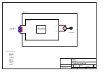
TegraPol-11, Circuit Diagram
<Cage Code>
G
Size
Scale
CAGE Code
DWG NO
Rev
Sheet
of
5
9
4
8
3
7
2
6
1
5
9
4
8
3
7
2
6
1
5
9
4
8
3
7
2
6
1
5
9
4
8
3
7
2
6
1
Содержание TegraDoser-1
Страница 1: ...TegraPol 11 15 TegraForce 1 Manual No 15517001 Date of Release 0 201 TegraDoser 1 Instruction Manual ...
Страница 6: ......
Страница 50: ...TegraPol 11 15 TegraForce 1 Handbuch Nr 15517001 Auslieferungsdatum 20 TegraDoser 1 Gebrauchsanweisung ...
Страница 101: ...TegraPol 11 15 TegraForce 1 Mode d emploi no 15517001 Date de parution 20 TegraDoser 1 Mode d emploi ...
Страница 106: ......
Страница 152: ...TegraPol 11 15 TegraForce 1 TegraDoser 1 Spare Parts and Diagrams Manual No 15517001 Date of Release 1 20 ...
Страница 159: ......
Страница 160: ......
Страница 162: ......
Страница 163: ......
Страница 164: ......
Страница 165: ......
Страница 166: ......


