34
il
d
Version
1
CHAPTER
8:
MAINTENANCE
Strongman
offers
warranty
as
per
Limited
Warranty
Statement
included
in
this
manual.
The
manufacturer
will
not
take
any
responsibility
for
improper
installation
and
operation,
overload
running,
improper
concrete
flooring
(that
cannot
meet
the
requirements
in
the
manual),
normal
mechanical
abrasion
and
insufficient
maintenance.
The
warranty
will
be
carried
out
on
the
basis
of
the
type
and
serial
number
of
the
equipment.
Therefore,
the
user
shall
provide
them
to
the
manufacturer
accurately.
The
several
types
of
maintenance
operations
to
be
carried
out
are
described
below.
Routine
maintenance
for
the
unit
will
reduce
maintenance
cost
and
prolong
the
lifetime.
The
listed
schedules
are
given
for
user
information
and
they
refer
to
normal
operating
conditions.
They
can
be
changed
according
to
the
kind
of
service,
environment,
frequency
of
use,
etc.
1.
DAILY
PRE-OPERATION
CHECK
The
user
should
perform
daily
check
of
safety
lock
device
.The
discovery
of
device
failure
before
using
the
left
will
save
you
from
expensive
property
damage,
lost
time
and
serious
personal
injury.
Check
safety
lock
audibly
and
visually
while
in
operation.
Check
hydraulic
connections
and
hoses
for
leakage.
Check
chain
connections,
cable
connections,
wiring
and
switch
for
damage.
Check
obstacles
under
platform.
2.
WEEKLY
MAINTENANCE
Check
the
cleanliness
of
all
parts.
Check
the
safety
lock
device
as
previously
described.
Check
hydraulic
connections
and
hoses
for
leakage.
Check
hydraulic
oil
level
on
tank
by
lowering
the
platform
completely
to
the
floor
and
check
the
o
level.
If
needed,
add
oil
but
should
find
where
is
the
leakage
to
solve
the
problem.
Recommende
Hydraulic
oil
(#
46).
Check
and
tighten
bolts,
nuts
and
screws.
Содержание Telford
Страница 1: ...Version 1 1 INSTALLATION MANUAL OPERATION INSTRUCTIONS SINGLE POST CAR PARKING LIFT ...
Страница 7: ...Version 1 7 WARNING SIGNS ...
Страница 8: ...Version 1 8 Fig 2 Fig 3 ...
Страница 11: ...Version 1 11 4 4 Lift Dimensions ...
Страница 20: ...Version 1 20 Fig 13 Fig 14 Fig15 Fig16 ...
Страница 21: ...Version 1 21 Fig 17 Fig 18 Fig 19 ...
Страница 24: ...Version 1 24 Fig 24 Fig 25 ...
Страница 25: ...Version 1 25 Lock device in the post Fig 26 Fig 27 ...
Страница 26: ...Version 1 26 Fig 28 ...
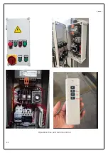
Страница 31: ...Version 1 31 Operation box and remote control ...
Страница 32: ...Version 1 32 OPERATION STEPS OF OPERATION PANEL CONTROL PANEL ...
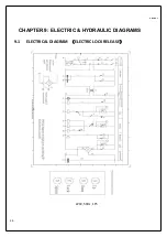
Страница 36: ...Version 1 36 CHAPTER 9 ELECTRIC HYDRAULIC DIAGRAMS 9 1 ELECTRICAL DIAGRAM ELECTRIC LOCK RELEASE 220V 50Hz 1Ph ...
Страница 38: ...Version 1 38 9 2 HYDRAULIC DIAGRAM ...
Страница 44: ...Version 1 44 NOTES ...

