Version 1
19
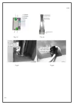
Fig.11
Fig.12
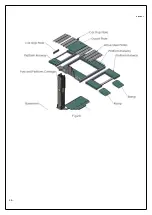
6.3: INSTALLATION OF CARRIAGE, CYLINDER & CHAIN INSIDE THE COLUMN (POST):
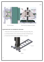
Carry carriage and post by
1. Insert the carriage (Fig 13) into the post from the top of the post (Fig 14).
2. Insert the chain pulley hole to the head of the cylinder.
3. Put the cylinder on the cylinder base seat at the bottom of the post (Fig 15).
4. Insert the chain inside the chain pulley and fix one side of the chain on the clamp behind the
cylinder base at the bottom of the post (Fig 16).
5. Fix the other side of the chain to the carriage using threaded connection rod M20 (Fig 17 & Fig 18).
6. Fix the cover on the top of the post using bolts M18 x 45.
Содержание Telford
Страница 1: ...Version 1 1 INSTALLATION MANUAL OPERATION INSTRUCTIONS SINGLE POST CAR PARKING LIFT ...
Страница 7: ...Version 1 7 WARNING SIGNS ...
Страница 8: ...Version 1 8 Fig 2 Fig 3 ...
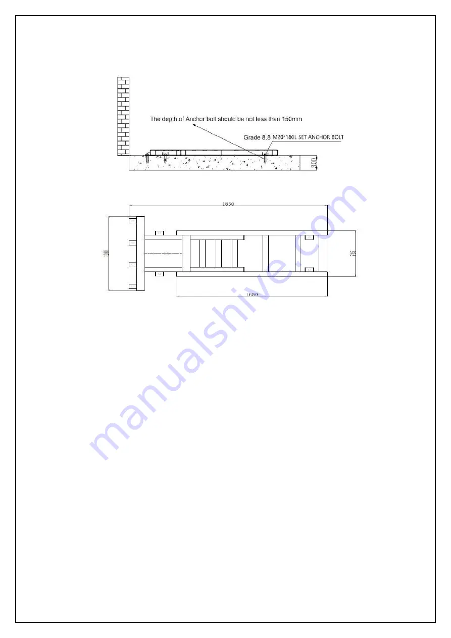
Страница 11: ...Version 1 11 4 4 Lift Dimensions ...
Страница 20: ...Version 1 20 Fig 13 Fig 14 Fig15 Fig16 ...
Страница 21: ...Version 1 21 Fig 17 Fig 18 Fig 19 ...
Страница 24: ...Version 1 24 Fig 24 Fig 25 ...
Страница 25: ...Version 1 25 Lock device in the post Fig 26 Fig 27 ...
Страница 26: ...Version 1 26 Fig 28 ...
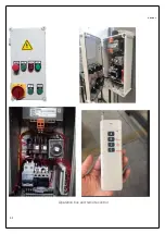
Страница 31: ...Version 1 31 Operation box and remote control ...
Страница 32: ...Version 1 32 OPERATION STEPS OF OPERATION PANEL CONTROL PANEL ...
Страница 36: ...Version 1 36 CHAPTER 9 ELECTRIC HYDRAULIC DIAGRAMS 9 1 ELECTRICAL DIAGRAM ELECTRIC LOCK RELEASE 220V 50Hz 1Ph ...
Страница 38: ...Version 1 38 9 2 HYDRAULIC DIAGRAM ...
Страница 44: ...Version 1 44 NOTES ...


