


Manifold
Mounting
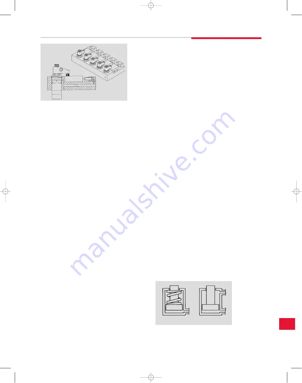
Manifold mounted components eliminate the need for external fittings,
tubing, and hoses because the fluid passages are machined directly
into the fixture. Securing the workholding component to the fixture
automatically makes the hydraulic connection.
Manifold Mounting:
Provides no-tool hydraulic connections
Saves valuable fixture space
Eliminates tubes, hoses or fittings that disrupt coolant
flow and collect chips
Simplifies post-machining fixture cleaning
Reduces assembly and maintenance time
Improves performance
Means fewer hydraulic connections resulting in fewer
potential leak points
Results in a cleaner, more professional-looking fixture
Plumbing Sizing
When designing and assembling your hydraulic system, keep in mind
that your choices of size and length of plumbing lines can significantly
change the performance of your fixture. The back-pressure created by
fittings, tubing and hoses can slow the operation of your system, especially
single-acting systems. Larger diameter plumbing runs with a minimum
number of bends and fittings will reduce this back pressure.
When sizing hydraulic lines, make sure you look at the inside diameter:
1⁄4" hose is not the same as 1⁄4" tubing. Hose is specified by its inside
diameter. Hydraulic tubing is usually specified by the outside diameter.
As example, 1⁄4" O.D., .035" wall tubing has an inside diameter of
.180", a flow carrying capacity of only 50% of that of the hose.
Single-acting clamps can develop only a limited amount of pressure to
force hydraulic fluid out of the clamp and allow it to retract. When the
return fluid from multiple clamps must share the same hydraulic line,
back pressure can easily become excessive and slow the
clamp’s retraction.
When connecting multiple clamps, you can use either a “daisy chain”
or “home run” configuration. In a daisy chain, you use a tee at each
clamp and run tubing from the first clamp to the second and then to the
third and then the fourth, etc. When using a home run configuration,
you begin at a manifold and run hydraulic lines all the way from the
manifold to each clamp.
The daisy chain method uses less tubing so it might appear that this
would minimize back pressure. However, in the daisy chain the fluid
from all of the clamps must pass through a single hydraulic line. In the
home run, while there may be longer runs, each line only has to
accommodate flow from one clamp.
The viscosity of the hydraulic fluid used will also affect back pressure.
Viscosity is affected by temperature. Contact the factory to discuss
applications running below room temperature. We recommend using
only DE-STA-CO fluids. Other fluids may have different viscosities or
other characteristics that can adversely affect system operation.
Single-acting vs. Double-acting
Another decision to be made early in the planning stage is whether to
use single-acting or double-acting components.
Single-acting components are typically actuated using hydraulic
pressure. When released, the pressure is removed and the actuator is
returned by a spring which forces the hydraulic fluid back into the
pump reservoir. This type of system is usually the most cost effective
because each actuator needs only one pressure source connection for
operation. Single-acting actuators should be vented to clean
atmosphere whenever appropriate. Remember to double the plumbing
for double-acting systems. This does, however, use more valuable
fixture space and adds to the cost.
Nevertheless, there are good reasons to use double-acting systems.
The larger and/or more complex the circuit design, the greater the
potential for return restrictions which will slow the return of the
single-acting actuators. Double-acting actuators are ideal for
applications which require both pushing and pulling or returning
clamps with heavy, custom designed attachments. They work well for
powering linkages which require fast actuation in both directions.
Double-acting clamps are often used in automated systems where
coordinating the action of the clamp with that of the rest of the system
requires fast, positive, predictable cycle times. By installing pressure
switches in both the pressure and return lines, the status of the clamp
can constantly be monitored.
DE-STA-CO
Subject to technical modifications without notice
15.9
S
tr
o
n
g
H
o
ld
C
la
m
p
in
g
S
y
s
te
m
T
M
System design information
Single-acting
Double-acting
15_StrongHold.qxp:15_DES_StrongHold-1-14.indd 1/2/08 9:03 AM Page 15.9