background image

Motherboard

Front USB Ports

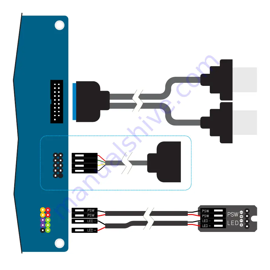
Connect Power Switch and USB Ports to the Motherboard

Motherboard layout, pinout and cable colours shown are for illustrative purposes only, actual configurations will 
vary between models and manufacturers. Please check your motherboard user guide for full details and 
information.

When connecting the power LED, ensure correct polarity otherwise the light will not illuminate.

19PIN USB3.0 Header

HDD+

HDD-

RESET
RESET

NC

PSW
PSW
LED-
NC
LED+

+5V
DA -
DA+
GND
N/C

USB 3.0

USB 3.0

Power Switch / Light PCB

Optional Accessory for USB2.0

9

Содержание FC8

Страница 1: ......

Страница 2: ... allen key for and Philips which if you don t have you really should go out and buy one PCS M x 3 6 6mm 3mm Philips Thread Cut etic M Diameter 3 Length 6 C S ounter unk Table of Contents COPYRIGHT NOTICE Copyright 2018 All Rights Reserved No part of this publication may be reproduced stored in a retrieval system or transmitted in any form or in any means by electronic mechanical photocopying recor...

Страница 3: ...USB 3 0 2 Optional USB2 0 Conversion Cable 1 x Low Profile Single Slot Expansion Card Max Length 230mm 80mm Height 20mm Width 240 250 108mm W D H Including Feet NanoPSU External AC Adapter Internal DC to DC converter 5 5mm Jack 2 IRRC or FLIRC IR Solutions 2 2 6KG Excluding CPU Cooler Assembly 1 Optical Version 2 Not Supplied With Case Top Panel Heat Sink Side Panel 1 Optical Drive Slot 1 Optical ...

Страница 4: ...y The drive tray is held in place by 4 screws which are all accessible from the top as shown Once all 4 screws are removed lift the drive tray out of the case The tray will have 2 x SSD brackets pre fitted which can also be removed If you have the Optical version of the FC8 the optical drive mounting bracket will be fitted and should also be removed from the tray Install the I O Shield Locate the ...

Страница 5: ...les The hole position will vary depending on the brand and model of CPU Peel the protective film from the adhesive pads and stick the nuts to the underside of the motherboard ensuring they correctly align with the holes The slightly raised rim of the nut should fit through the motherboard and protrude slightly from the top side of the PCB Install the Motherboard Carefully lower the motherboard int...

Страница 6: ...the surfaces indicated below We recommend first trying the assembly without applying thermal paste as this will allow you to test and adjust the alignment without making a mess Once you have a good approximation of the positioning apply thermal paste initially to the lower CPU mount heat pipe grooves then lock the heat pipes between the upper and lower CPU mounts using the 4 HEX screws The screws ...

Страница 7: ...ghtened and only require 4 5 turns from the point the spring start to compress HCH M3x10 Fit the Cooler Assembly to the Heat Sink CPU Carefully lower the CPU mount heat pipe assembly into the case and place it onto the CPU ensuring the heat pipes the area with thermal paste applied only make contact with the heat sink once the assembly is resting centrally on the CPU Adjust the CPU mount arms so t...

Страница 8: ...m input power jack For more details on installing the PSU and optional IR module refer to their user guides The power button indicator light connects to the motherboard front I O header see diagram on next page for wiring details The case is fitted with USB3 0 ports which require a 19PIN USB3 0 header on the motherboard If your motherboard does not have an internal USB3 0 header it is still possib...

Страница 9: ...configurations will vary between models and manufacturers Please check your motherboard user guide for full details and information When connecting the power LED ensure correct polarity otherwise the light will not illuminate 19PIN USB3 0 Header HDD HDD RESET RESET NC PSW PSW LED NC LED 5V DA DA GND N C USB 3 0 USB 3 0 Power Switch Light PCB Optional Accessory for USB2 0 9 ...

Страница 10: ... by side Where you position the drives on the slots is up to you and what works best to avoid conflicts with other hardware installed There are 5 slots that run the length of the tray slot 1 is shared by 3 5 and 2 5 drives slot 4 is exclusively for 2 5 drives and the other 3 slots are for 3 5 drives depending on their orientation To attach a drive align the mounting holes on the underside of the d...

Страница 11: ...efore fully tightening the screws position the drive as far forward as possible without the eject button being depressed If the screws meet any resistance from internal components of the optical drive do NOT tighten that screw any further it could damage the mechanism Once secured to the bracket test the eject button can function correctly Depending on the eject button position and height a rubber...

Страница 12: ...re 2 screws per drive and has 2 fixed mounting locations Optical version of FC8 can only use the rear location If you have the OPTICAL version of the FC8 secure the optical drive in place with the 4 screws as shown but DO NOT fully tighten the screws Only after you have secured the drive tray back into the case should these screws be tightened as you will need to adjust the position of the drive t...

Страница 13: ... To install a low profile expansion card begin by removing the pre installed PCI blanking plate and the PCI mount which is secured to the back panel with 2 screws Removing the PCI mount will give the extra clearance required on the rear panel opening to install the card Note that this procedure is shown prior to replacing the drive tray as this give more room to work with but it can also be instal...

Страница 14: ...ay in place and connect all the drive cables Adjust the Optical Drive Adjust the position of the optical drive eject bar so that its flush with the front inside edge of the case and the eject button protrudes 1 2mm from the front face of the case Test that the button operates correctly by listening feeling for the button click when pressing the eject button Once the correct position has been found...

Страница 15: ...ssembled and closed all that remains is to connect the power and I O cables to the appropriate ports When positioning your case please consider an area out of direct sunlight with adequate natural air flow and a moderate ambient room temperature PCS M3x8 PPH M3x8 IMPORTANT NOTICE Passively cooled products can get hot to the touch especially when running at high loads for extended periods This is a...

Страница 16: ...Designed in Europe Printed in China Copyright 2018 All Rights Reserved ...

Отзывы: