Vision.net RS232 Interface Port
Installation & Operation Guide
3
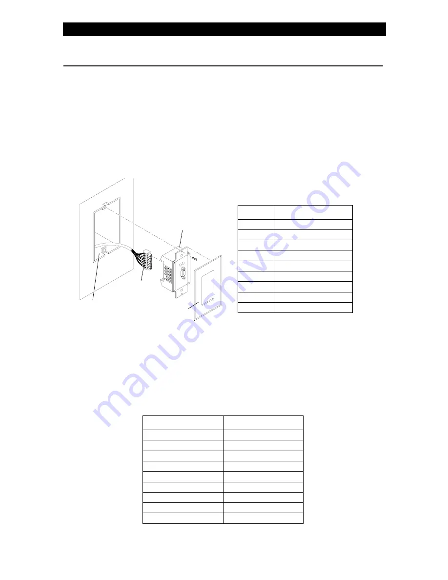
INSTALLATION
The Vision.net Network consists of a single CAT5e cable connecting all modules in a daisy
chain manner. All units connect to the network using a 9-pin plug-in connector (included).
Installation Steps
Step
1. Unpack unit and inspect for any signs of shipping damage. Ensure that two
mounting screws are included.
Step
2. Connect Vision.net Network Cable to 9-pin connector at back of RS232 Interface
Port.
Step
3. Insert RS232 Interface Port into standard deep rough-in box (not included). Secure
with two supplied mounting screws.
Step
4. Snap faceplate into place.
A standard Windows-compatible computer can be connected to the Vision.net Network using
the RS232 Interface Port. The port accepts a standard one-to-one 9-pin serial cable up to 25
feet in length.
RS232 Interface Port
PC Computer
Pin 1 (NU)
Pin 1 (NU)
Pin 2 (TX)
Pin 2 (RD)
Pin 3 (RX)
Pin 3 (TD)
Pin 4 (NU)
Pin 4 (NU)
Pin 5 (GND)
Pin 5 (GND)
Pin 6 (NU)
Pin 6 (NU)
Pin 7 (CTS)
Pin 7 (RTS)
Pin 8 (RTS)
Pin 8 (CTS)
Pin 9 (NU)
Pin 9 (NU)
9-Pin
RS232
Faceplate
Connector
Interface
Rough-In Box
(not included)
Pin
Signal
1
WH/OR (+ Data)
2
OR (- Data)
3
SHIELD
4
WH/GN (+ Volts)
5
GN (Ground)
6
WH/BL (+ Volts)
7
BL (Ground)
8
WH/BR (+ Volts)
9
BR (Ground)
9-Pin Connector Wiring


