background image

Disposal Instructions 

29

Replacing the Solid State Disk

If necessary, you can replace the Solid State Disk in the appliance with 

another one of the same model.

To replace the Solid State Disk

1.

Connect to the engine command line as described in 

Connecting 

to the Engine Command Line

 (page 27).

2.

Shut down the engine:

If the appliance is powered on, press 

Enter

, log in as the user 

root

 with the password you have set for the appliance, and 

issue the command 

halt.

3.

Unplug all power cords from the system or the wall outlets.

4.

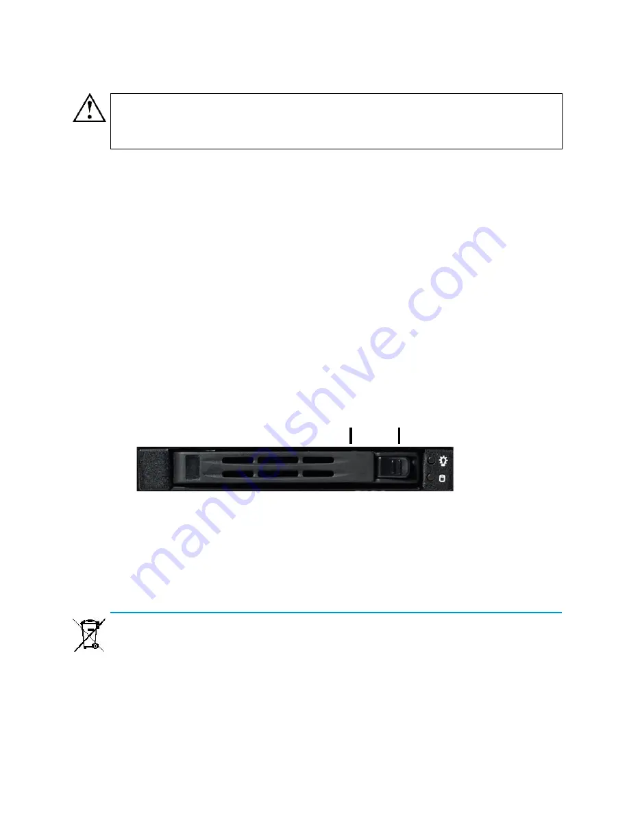
Locate the Solid State Disk drive on the appliance’s back panel 

(see the illustration in 

Back Panel

 (page 9)).

5.

Press the release button to release the lever that locks the disk 

into position.

6.

Pull the lever carefully to remove the disk from the drive.

7.

Press the release button on the new disk to release the lever.

8.

Insert the disk into the drive.

9.

Press the lever down to lock the disk into position.

Disposal Instructions

Dispose of the appliance separately from household waste at an 

appropriate waste disposal facility at the end of its useful service life.

Caution – 

We recommend using a grounding strap when handling a 

Solid State Disk (SSD). Uninstalled SSDs are sensitive to ESD 

damage.

Release button

Lever

Содержание StoneGate IPS-1205

Страница 1: ...Appliance Installation Guide IPS 1205...

Страница 2: ...ribed in these materials are provided pursuant to the general terms for support and maintenance services and the related service description which can be found at the Stonesoft website www stonesoft c...

Страница 3: ...which can be found at the Stonesoft website Contents Installation Procedure 4 Product Documentation 4 Safety Precautions 5 Unpacking the Appliance 7 Front Panel 7 Back Panel 9 Rack Mounting 10 Connect...

Страница 4: ...l Configuration page 18 Product Documentation Press F1 in any Management Client window to view the Online Help All PDF guides are available On the Management Center CD ROM in the Documentation folder...

Страница 5: ...ed on electrical equipment This is to avoid making a complete circuit which will cause electrical shock Use extreme caution when using metal tools which can easily damage any electrical components or...

Страница 6: ...each other An electrical discharge is created to neutralize this difference which can damage electronic components and printed circuit boards Use a grounded wrist strap designed to prevent static dis...

Страница 7: ...necting the Cables page 16 The front panel indicator lights are explained below Caution Do not change the battery the battery must be replaced by authorized service personnel only Danger of explosion...

Страница 8: ...s LED is illuminated when the system is operating normally Yellow The appliance is in standby mode Warning Red Overheat alert Blinks on fan failure Disk Activity Green Indicates hard drive activity wh...

Страница 9: ...tate Disk SSD Drive are explained below Table 3 SSD Drive Indicators Indicator Status Explanation Power Blue A Solid State Disk is in the drive Disk Unlit This indicator is not currently used AC or DC...

Страница 10: ...electrical noise and electromagnetic fields are generated Leave enough clearance in front of the rack to enable you to open the front door completely 63 cm 25 inches Leave enough clearance in the back...

Страница 11: ...vent components falling off of the appliance Be sure to install an AC power disconnect for the entire rack assembly This power disconnect must be clearly marked The rack assembly must be properly grou...

Страница 12: ...3 Repeat step 2 on the other side of the appliance 4 Attach each bracket to the rack with two screws through the holes in the front of the bracket one screw through the top hole and another through th...

Страница 13: ...kets that attach to the appliance and two longer brackets that attach to the rack 2 Attach a short bracket to the appliance with two screws 3 Repeat step 2 on the other side of the appliance 4 Attach...

Страница 14: ...one screw through the top hole and another through the bottom hole Proceed to Connecting the Cables page 16 To install the appliance with long brackets 1 Locate the two pairs of brackets in the delive...

Страница 15: ...rails to the rack the rails are marked with L for left and R for right and lock the rails into position by pushing the yellow locking tabs up For additional security you can also attach the rails to...

Страница 16: ...cables accordingly Cable Types Always use standard cabling methods with inline IPS use crossover cables to connect the appliance to hosts and straight cables to connect the appliance to switches hubs...

Страница 17: ...the lower speed Connecting the Appliance to the Power Supply To connect the appliance to the power supply 1 Connect the power cable to the power connector on the back of the appliance 2 Plug the power...

Страница 18: ...figure the engine manually See Using the Engine Configuration Wizard page 19 Configuring the Engine Automatically The automatic configuration requires that you have a suitable configuration saved on a...

Страница 19: ...heck the IP addresses you have defined in the Management Client If the configuration with the USB stick still does not succeed remove the USB stick from the USB port and follow the instructions for th...

Страница 20: ...ort option select the configuration file To set the keyboard layout 1 Highlight the entry field for Keyboard Layout using the arrow keys and press ENTER The Select Keyboard Layout dialog opens 2 Highl...

Страница 21: ...et the rest of the OS settings 1 Type in the name of the engine 2 Type in the password for the user root This is the only account for engine command line access Note The timezone setting affects only...

Страница 22: ...k Make sure that the speed duplex settings of network cards are identical at both ends of each cable Also make sure that the speed duplex settings of inline interfaces match the speed duplex settings...

Страница 23: ...e can be useful during IPS appliance deployment when bypass network interface pairs on the appliance are in the Normal mode Initial bypass allows traffic to flow through the IPS appliance until the in...

Страница 24: ...Client To activate the Initial Configuration 1 Highlight Switch to Initial Configuration and press spacebar to activate 2 Fill in the IP Address Netmask and Gateway to Management information accordin...

Страница 25: ...third part of the configuration you select whether you want this engine to work as a Sensor an Analyzer or a combined Sensor Analyzer depending on the appliance you have purchased The selection you ma...

Страница 26: ...the connection state is Connected indicating that the Management Server can connect to the node The next step is installing a security policy on the engine to replace the initial configuration you jus...

Страница 27: ...the appliance does not start up with the new version it automatically switches to the previous configuration at the next reboot You can also switch back to the previously installed software version ma...

Страница 28: ...reset If you decide to cancel the operation type NO and press Enter To use the appliance after a factory reset you must configure it as explained in Initial Configuration page 18 Note If the certific...

Страница 29: ...ets 4 Locate the Solid State Disk drive on the appliance s back panel see the illustration in Back Panel page 9 5 Press the release button to release the lever that locks the disk into position 6 Pull...

Страница 30: ...documentation See inside for further details All documentation and our technical knowledge base is available at www stonesoft com support Copyright 2010 Stonesoft Corporation Stonesoft Inc Americas He...

Отзывы: