2400 User Manual
Copyright © 2004 Stoneridge Electronics Ltd
25
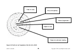
Figure 14: Fields to be Completed at the Start of a Shift.
Driver’s name.
Place of Departure.
Vehicle Registration.
Departure date.
Departure odometer reading.
Страница 1: ...2400 User Manual Copyright 2004 Stoneridge Electronics Ltd 1...
Страница 2: ...ngers of causing damage to the tachograph there is also a legal obligation to remove the charts after 24 hours of use Disconnect the electrical supply to the tachograph if Electrical welding is carrie...
Страница 3: ...THE TIME SETTING 10 3 1 Clock Setting For Units Without Real Time Clock RTC 10 3 2 Clock Setting For Units With Battery Backed Real Time Clock RTC 10 4 0 MODE SETTING 11 4 1 Normal and Trip Modes 11...
Страница 4: ...ce When Operator Action Required 19 Figure 4 Drawer Ejection Position of the Safe Push Position 20 Figure 5 Opening of the Tachograph Drawer 20 Figure 6 Display in NORMAL Mode 21 Figure 7 Display in T...
Страница 5: ...produce a fourth trace to record events such as off road driving or engine revolution recording The drawer which contains the charts the display and the controls is electro mechanically held in the lo...
Страница 6: ...Figure 1 Illustration of the Controls Driver 2 Duty Button Driver 1 Duty Button Driving Other Work LED see Page 7 Non driving Other Work LED see page 7 Drawer Eject Button Rest LED PUSH here for Drawe...
Страница 7: ...activity modes which correspond with the activities defined in the Council Regulation EEC 3821 85 4 indicates working used to record non driving active work such as loading a vehicle etc 1 indicates a...
Страница 8: ...on 2 4 Advance Push button The Advance push button which is identified by a white plus sign is used to reset the trip value to zero and to alter individual field settings of the digital clock Setting...
Страница 9: ...are available NORMAL TRIP DTC VALUE DISPLAY MODE and DTC TIME AND DATE DISPLAY MODE Note For the 12V version only Normal and Trip Modes are available The digital display features the following three d...
Страница 10: ...ange Push button O When the left hand field is flashing press the Advance push button repeatedly until the correct hour time is flashing Minutes right hand field Press the Mode Change Push button O Wh...
Страница 11: ...odes are available by pressing the Mode Change push button O only In both modes the display shows the current set time In the NORMAL mode the upper right hand area of the display shows the odometer wh...
Страница 12: ...drive mechanism can be rotated easily by hand When the drawer is closed the drive mechanism is automatically driven to a position corresponding with the current time setting During normal operation if...
Страница 13: ...e corresponding pear shaped drive spindle Figure 12 Method of Crew Chart Insertion page 23 The Driver chart can now be inserted as described below 5 2 Driver Chart Insertion If the tachograph drawer i...
Страница 14: ...ring forward to the partly open position The LEDs then revert to the most recently selected Duty mode status The drawer can now be carefully pulled out to its fully extended position as shown on Figur...
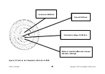
Страница 15: ...lank chart is provided to the driver and to the crew member in the case of two person operation A chart requires the fields identified on the diagram shown in Figure 14 to be manually filled in Note F...
Страница 16: ...condition occurs after 24 hours of non activity Note Power down will not occur if the drawer is open 10 0 CARE AND MAINTENANCE OF THE TACHOGRAPH 10 1 Cleanliness Ensure that the tachograph drawer is C...
Страница 17: ...s in which the LEDs cycle automatic functions and alternately flash indicating that operator intervention is required previously detailed in the Description of the Controls section override any of the...
Страница 18: ...ror Yes CANbus in passive error mode Check tachograph settings possibly no CANbus present in vehicle 9430 V pulse Output Error Yes Monitoring of V Pulse output Disconnect all V pulse supported equipme...
Страница 19: ...2400 User Manual Copyright 2004 Stoneridge Electronics Ltd 19 Figure 2 LED Sequence When Tachograph Carrying out Automatic Functions Figure 3 LED Sequence When Operator Action Required...
Страница 20: ...2400 User Manual Copyright 2004 Stoneridge Electronics Ltd 20 Figure 4 Drawer Ejection Position of the Safe Push Position Figure 5 Opening of the Tachograph Drawer...
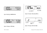
Страница 21: ...2400 User Manual Copyright 2004 Stoneridge Electronics Ltd 21 Figure 6 Display in NORMAL Mode Figure 7 Display in TRIP Mode Figure 8 Display in Clock Adjust Mode Figure 9 Display in DTC Value Mode...
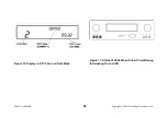
Страница 22: ...2400 User Manual Copyright 2004 Stoneridge Electronics Ltd 22 Figure 10 Display in DTC Time and Date Mode Figure 11 Status of LEDs When Driver Chart Missing Alternating On and Off...
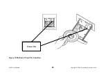
Страница 23: ...2400 User Manual Copyright 2004 Stoneridge Electronics Ltd 23 Figure 12 Method of Crew Chart Insertion Drawer Slot...
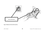
Страница 24: ...2400 User Manual Copyright 2004 Stoneridge Electronics Ltd 24 Figure 13 Method of Driver Chart Insertion Driver chart location...
Страница 25: ...er Manual Copyright 2004 Stoneridge Electronics Ltd 25 Figure 14 Fields to be Completed at the Start of a Shift Driver s name Place of Departure Vehicle Registration Departure date Departure odometer...
Страница 26: ...right 2004 Stoneridge Electronics Ltd 26 Figure 15 Fields to be Completed at the End of a Shift Location at Shift End Date at Shift End Odometer reading at Shift End Distance travelled difference betw...
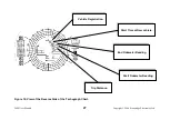
Страница 27: ...ual Copyright 2004 Stoneridge Electronics Ltd 27 Figure 16 View of the Reverse Side of the Tachograph Chart Vehicle Registration Start Time at New vehicle End Odometer Reading Start Odometer Reading T...
Страница 28: ...laws which are enforced by the National Authorities It is imperative that any tachograph servicing or repair is carried out ONLY at government approved centres This complies with the law see Council...