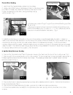
Stillwater Designs KICKER 19119147 Скачать руководство пользователя страница 3

3

Power Wire Routing

1. Disconnect the negative battery cable from the battery.
2. Using a razor knife make a cross shaped incision in the large rubber 
grommet from inside the vehicle and feed the power wire from the 
engine compartment to the cabin. Using a fi sh tape wire is 
recommended.  Fig. 1.

3. Pull the power wires through the grommet until the sheathing touches 
the grommet.
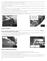
4. Remove the fuse box cover under the hood and connect the power 
wires to the accessory lug. Torque to 9, +/- 1.5 Nm. Make sure that the 
wires exit on the side closest to the battery.   Fig. 2

5. Install the white three pin connector on the end of the amplifi er power harness inside the cabin.  It does not 
matter what order the three wires are in on the three pin connecter, but the terminals can only be inserted one way.  
If the terminal will not go into the connecter, simply rotate it 180 degrees and try again.  Push the terminals in 
until they click and lock into place.  Install the black two pin connector on the end of the subwoofer power harness 
inside the cabin.  The black connector should have a block out plug installed in one side to prevent the power wire 
from being inserted into the wrong position in the connector.

Amplifi er Body Harness Routing

6. Remove the driver’s side kick/threshold panel by loosening the retainer at the top and then pulling loose. Fig. 3
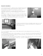
7. Remove both of the covers directly in front of the console.  On the driver’s side, remove the plastic retainer with a 
Phillip’s head screwdriver and then pull the cover loose.  The passenger’s side has no plastic retainer and can 
simply be pulled off. Fig. 4 

8. Remove the radio trim bezel by carefully prying loose with a plastic panel removal tool.  Start at the corners and 
work around the bezel. Fig. 5
9. Remove the four screws securing the radio, pull radio from dash and disconnect all wiring.  
10. Route the amplifi er body harness from the right side of the radio opening down to the area in front of the 
console.

  Cut grommet here. 

Fig. 1 


Fig. 2 

Wires should exit in 

direction of arrow 


Retainer – Rotate 

counter-clockwise 

Fig. 3 


Fig. 4 

Содержание KICKER 19119147

Страница 1: ... 19119147 Designed for 2012 and newer Chevrolet Sonic vehicles Amplifier Bracket Assembly 25A Fuse Wire Ties x6 Amplifier Power Harness Amplifier Body Harness 2012 Stillwater Designs 19119147 A1 20120615 ...

Страница 2: ...2 Subwoofer Assembly Subwoofer Power Harness 15A Fuse Wire Ties x6 Foam Strip Wire Taps x2 Subwoofer Body Harness ...

Страница 3: ... place Install the black two pin connector on the end of the subwoofer power harness inside the cabin The black connector should have a block out plug installed in one side to prevent the power wire from being inserted into the wrong position in the connector Amplifier Body Harness Routing 6 Remove the driver s side kick threshold panel by loosening the retainer at the top and then pulling loose F...

Страница 4: ...s side kick panel Torque to 9 1 5 Nm Fig 6 Amplifier Installation 16 Remove the three nuts securing the SIR module on the center hump in front of the console Fig 7 Do not disconnect the wiring from the module 17 Lift the module off the studs and set the amplifier bracket assembly over the studs Reinstall the module over the studs and on top of the amplifier bracket and retighten the nuts Fig 8 18 ...

Страница 5: ...roximately 2 3 inch long Fig 9 25 Place the supplied foam strip on the plastic quarter panel cover in the position shown in Fig 10 to prevent the enclosure from contacting the panel Hatchback only 26 On the hatchback models remove the intermediate load floor Intermediate load floor cannot be used with subwoofer installed 27 Lay the poly bag that the subwoofer is packaged in on top of the carpet be...

Страница 6: ...firewall to make sure it is plugged in securely Check the inline connectors near the subwoofer enclosure to make sure they are plugged securely Check the ground wire connection to make sure it is tightly secured to the proper ground in the vehicle Check the audio input signal connection to make sure it is secure and connected to the proper wiring Test with different music in case there is no low f...

Страница 7: ...low frequency information in music Test with several different songs Subwoofer harness not properly completely connected to subwoofer Securely fasten both of the connectors on the subwoofer harness to the subwoofer Check for loose connections Radio Not Coming On Radio connector not properly completely connected Check radio connector to insure it is completely seated Blown radio fuse Refer to owner...

Страница 8: ...8 ...

Отзывы: