background image

© 2007 Stevens AeroModel.  


Page 32 of 33 


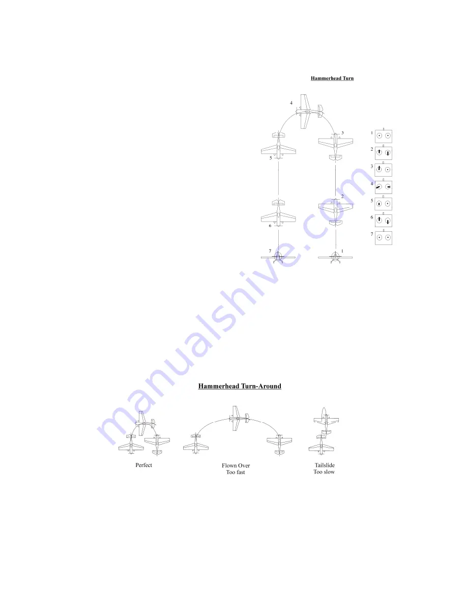
The Hammerhead Turn 


Begin the hammer head turn from a level line with enough throttle to 
draw a long vertical upline – but not so much that the model climbs 
so high that it is hard to see.  Execute a 1/4 loop up to a vertical line.  
Establish and correct for a good vertical line.  You will probably need 
to add right rudder during the pull up to maintain good yaw balance 
on the upline.  As the model decelerates, add right aileron to counter 
torque’s tendency to roll the model to the left.  This will increase as 
the model slows.  Adjust the throttle to maintain a slow deceleration, 
up to and including reducing the throttle enough to “stop” at the point 
that you want.  Do not close the throttle at the top of the maneuver, 
as we need thrust over the rudder to intitiate the turn-around.  A 
good technique is to reduce the throttle to a point that allows a slow 
deceleration and stop point, and maintain that throttle setting 
through the entire turn-around. 
 
At the precise moment that the model stops vertical motion, add full 
left rudder, and increase the right aileron to maintain a true vertical 
track (no wing torque) during the turn-around.  The model should 
pivot within one wingspan diameter, to a nose down position.  During 
your first few hammerhead turns, you will need to adjust the amount 
of rudder, and aileron needed to rotate the model to the vertical 
downline.  For most of my models, I end up using full left rudder and 
½ right aileron.  If you use too little aileron, the model will torque at 
the top of the hammerhead.  Torquing is the tendency of the model, 
at very slow airspeeds, to roll to the left in responseto the effects of 
torque. 
 
The point at which you add rudder for the turn-around portion of the maneuver is also something that will take time and 
experience to perfect.  Some models don’t have enough rudder authority to rotate the nose rapidly enough at zero forward 
(vertical) motion, so the turn-around will have to occur earlier.  The point at which you initiate the turn-around is often 
referred to as the “kick point” (in full scale aerobatics the rudder is on the foot controls, thus the “kick” of rudder for the 
turn-around). 
 
If the “kick point” is early, the model will fly over the top of the hammer (rather than a tight pirouette), and the radius of the 
turn-around will be too large.  If the “kick point” is late, the model may actually descend backwards (tailslide).  A perfect 
“kick” will make the model rotate within one wingspan radius to a vertical nose-down position.  Adjust the airspeed at the 
“kick point” to perfect the turn-around.  
 
Once the model transitions to the vertical down position, your work is not done.  Make sure that you actually establish the 
vertical downline.  Depending upon the quality of the turn-around, you will have to correct in pitch, roll, and yaw to re-
establish the vertical.  Finish the maneuver with a normal ¼ loop to a level line. 


Here’s to blue skies, calm winds, round loops, and soft touchdowns 

Good luck with your new model!! 


www.rcpilotguide.com 


Содержание SHAFT S400

Страница 1: ...2007 Stevens AeroModel Page 1 of 33 SHAFTS400 Instruction Manual Version 1 03 Revised 03 28 2013 Span 39 in Length 35 in Area 340 Sq In Weight 14 18 oz Made in the USA Of U S and Imported Parts...

Страница 2: ...s in both material and workmanship at the date of purchase This warranty does not cover any component parts damaged by use or modification In no case shall Stevens AeroModel s liability exceed the ori...

Страница 3: ...eel Retainers 2 4 40 Blind Nut 2 4 40 x 3 8 Nylon Bolt 2 3 16 Neo Magnet 2 1 8 x 3 1 2 Hardwood Dowel 1 Pair Du Bro RC 1 3 4 in Super Lite Wheels DUB175SL 1 3 16 x 3 1 2 Hardwood Dowel 1 Laser Cut Bas...

Страница 4: ...2007 Stevens AeroModel Page 4 of 33 Laser Cut Parts Inventory...

Страница 5: ...2007 Stevens AeroModel Page 5 of 33 Laser Cut Parts Inventory...

Страница 6: ...m a more experienced builder pilot Best Regards Bill Stevens bill stevensaero com Stevens AeroModel Built to Fly P O Box 15347 Colorado Springs CO 80935 Assembly Tips READ THE INSTRUCTIONS and the pla...

Страница 7: ...t is time to install the carbon fiber trailing edge re enforcement Locate the carbon fiber bar stock and use the plan sheet as a reference to cut the stock to length Heavy duty scissors or a fine razo...

Страница 8: ...s Assemble F7a and F7b to create one F7 former Assemble H2a and H2b to create H2 battery hatch Note make certain scribe lines running lengthwise along H2 components are on the same side See illustrati...

Страница 9: ...ccessful tack glue each of the crutch parts together Finally tack glue both 3 32 balsa fuselage sides to the crutch at tab and notch locations as illustrated below 6 F1 will bear a considerable load f...

Страница 10: ...1 16 plywood former F6 and key it to balsa former F11 and fuselage sides as illustrated below Square fuselage to building board and tack glue parts into position at tab and notch locations VERY IMPORT...

Страница 11: ...tall 1 16 plywood former SR3 to each side of the assembly within the fuselage as illustrated in the second photo below 13 Complete the mid section of the aft fuselage assembly by first installing the...

Страница 12: ...H1 While holding the hatch assembly flat on your work surface proceed to wick liberal amounts of thin CA between parts Finally glue one of the 3 16 diameter neo magnets into the 3 16 diameter hole as...

Страница 13: ...nent marker Install the second magnet with the marked side facing out Double check that when the hatch is installed to the fuselage it will be attracted to the catch Glue the magnet to the catch assem...

Страница 14: ...2a and S2b to create two 2 spar web caps T1a and T1b to create trailing edge Assemblies are joined along the pre cut scarf joints Reference parts along a straight edge and bond at the scarf joints usi...

Страница 15: ...he lower spar cap 5 Install the 1 32 plywood SR1 servo pocket to assembly by aligning tabs of SR1 to notches in rib R2 and S1 spar web Go ahead and bond SR1 in place making certain it is firmly seated...

Страница 16: ...the spar and wing ribs at the leading edge of W3 Dry fit all W3 parts to pull the wing assembly square Next key the 1 8 balsa wing tips W5 to the assembly and tack into position with a drop of CA glue...

Страница 17: ...balsa and use it to reference the proper installation height of W1 and W2 11 Install the leading edge stock First join the two 2 24 lengths of the provided 3 16 square balsa stock together using the...

Страница 18: ...Install the 1 32 plywood W4 trailing edge re enforcement within the notch at the wing trailing edge center section 15 Final glue all wing assembly parts For the most part we have been utilizing thin C...

Страница 19: ...ing edge should be sanded flush with the profile of only ribs R1 and R5 and remain proud of the mid span ribs by 1 16 see step 10 and use scrap 1 16 balsa as a guide A razor plane makes short work of...

Страница 20: ...and a chamfer or round the edges of the dowels With constant pressure and a gentle twisting motion work the dowels through the holes in the fuselage sides Remove dowels and harden holes with Thin CA 2...

Страница 21: ...d parts F14a F14b and F14c With the required parts in hand begin assembly by bonding F14b atop F14a Note that F14a is scribed to assist with the proper location of F14b Finally glue F14c on top of F14...

Страница 22: ...ts and using a sharp razor blade cut the bolt length down to 3 8 The cut to length bolts will pass through the tail skid then through the horizontal stabilizer and secure into the blind nuts that were...

Страница 23: ...Hitec HS 55 or similar servos Reference the plan sheet for servo locations Your elevator and rudder servos should be installed in the aft servo pockets of the fuselage just forward of the horizontal s...

Страница 24: ...ty Warped structure Check wing and tail surfaces over carefully looking for signs of twists or warps that will need to be removed prior to flying In the unlikely event that you have a warped surface h...

Страница 25: ...2007 Stevens AeroModel Page 25 of 33 THIS PAGE HAS BEEN PROVIDED TO SCHEME A COLOR SCHEME...

Страница 26: ...2007 Stevens AeroModel Page 26 of 33...

Страница 27: ...time he has flown as a First Officer on the Boeing 737 200 737 300 Airbus A320 Boeing 767 757 and as a Captain on the Boeing 737 300 While learning to fly and working as an instructor Scott s interest...

Страница 28: ...it is pointing very nose low Recovery from the spin will require control inputs that are very unnatural to pilots Even though we are pointing almost straight down we have a very high angle of attack...

Страница 29: ...cruising speed Any faster than this while dramatic is too fast to practice the pitch and yaw adjustments during the roll From a level line apply left aileron to start the roll to the left Adverse yaw...

Страница 30: ...leed off energy and end up in a spin Recovery from spins should be second nature before proceeding to snap rolls Be sure to start at an altitude that will allow a half loop recovery from a failed mane...

Страница 31: ...pon reaching the level inverted position and possibly a little bit before you reach level if you aren t averse to a bit of cheating roll to the left to upright flight The airspeed will be slower than...

Страница 32: ...most of my models I end up using full left rudder and right aileron If you use too little aileron the model will torque at the top of the hammerhead Torquing is the tendency of the model at very slow...

Страница 33: ...on line cart the discount will be applied regardless of payment option This offer is only available at www stevensaero com About the Book Written by an accomplished full scale pilot and R C pilot Mas...

Отзывы: