


SMC Series Chillers
Page 35
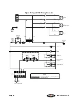
Figure 16: SMC Wiring Schematic for Chillers with No Pump or Reservoir
1T
1T
1FU
1FU
X1
1
1
Jumper
Remote
interlock
by others
1S
1S-1LT
5
7
6
1C
Condensing unit
contactor
G
1S-1LT
G
"Power On"
ON/OFF
1L1
1L2
1L1
1L2
2
Control
power
1PS
1PS
2PS
1
1CNTL
RED
(-)
YEL
(+)
Type K thermocouple
Subpanel
ground
1C
1T1
1T2
1MTR
Compressor
230V
115V
Jumper
6
2
7
3
8
4
9
5
10
ground
Earth
"Low Refrig
Pres"
3LT
R
4LT
R
Pres"
"High Refrig
2
4
5
1FLS
1FLS
G
5LT
G
2LT
R
"No Flow"
"Compressor On"
1
3
2T2
2T1
2MTR
Fan
Legend
Customer wiring/Customer-supplied components
Optional components
2
Содержание 30F to 65F
Страница 12: ...Page 12 SMC Series Chillers Figure 4 SMC Cast Iron Centrifugal Pump Curve 1 3 hp 0 249 kW ...
Страница 20: ...Page 20 SMC Series Chillers Figure 8 SMC Component Identification ...
Страница 36: ...Page 36 SMC Series Chillers Notes ...
Страница 40: ...Page 40 SMC Series Chillers Notes ...
Страница 41: ...SMC Series Chillers Page 41 Notes ...
Страница 42: ...Page 42 SMC Series Chillers Notes Technical Assistance ...