background image

PP500 LED lighting controllers - User Manual

Copyright and disclaimer notice

Except as prohibited by law:

All hardware, software and documentation is provided on an ‘as is’ basis. This
information is for guidance only. Installers must perform their own risk assessment
specific to each installation.

It is essential that the user ensures that the operation of the product is suitable for their
application.

The user must ensure that incorrect functioning of this equipment cannot cause any
dangerous situation or significant financial loss to occur.

Deliberate acts of endangerment and vandalism are not covered by this document and
must be considered by the installer.

While care has been taken in the preparation of this document Gardasoft Vision Ltd will
not accept any liability for consequential loss of any kind except those required by law.

All trademarks acknowledged. Hardware, software and documentation are
Copyright 2002 – 2018 Gardasoft Vision Ltd.

EC conformity declaration

The EC Certificate of Conformity is available from Gardasoft Vision Ltd on request

Issue status of this document: Issue 020 (January 2018)

PP500 LED lighting controllers - User Manual

Contents

1

Getting started

5

2

Safety

6

2.1

Heat

6

2.2

Electrical

6

2.3

General

7

2.4

Installation guidance (disclaimer)

7

3

Sicherheit

8

3.1

Wärme

8

3.2

Elektrik

8

3.3

Allgemein

9

3.4

Installationsanleitung (Haftungsausschluss)

10

4

Sécurité

11

4.1

Chaleur

11

4.2

Électricité

11

4.3

Généralités

12

4.4

Guide d'installation (clause de non-responsabilité)

13

5

General description

14

5.1

Output modes

14

5.1.1

Continuous

14

5.1.2

Pulsed

14

5.1.3

Switched

15

5.2

Triggers

15

5.3

Flags

15

5.4

Automatic light sensing

15

5.5

Cold start

15

6

Mechanical fixing

16

7

PP500 heat output

18

7.1

Heat output per channel

18

7.2

Total heat output

18

8

Connections

20

8.1

Triggers

20

8.2

Power supply

21

8.3

Wiring

21

9

Front panel configuration

22

9.1

Startup

22

9.2

Setting the light rating

22

9.3

Setting up continuous output

23

9.4

Setting up switched output

24

9.5

Setting up pulsed operation

25

9.6

Setting pulse delay and width times

27

10

Reference information

30

10.1

Timings

30

10.2

Specifications

30

10.3

Error codes

31

WWW.STEMMER-IMAGING.COM

Содержание Gardasoft PP500

Страница 1: ...PP500 LED Lighting Controllers Issue 020 User manual www gardasoft com WWW STEMMER IMAGING COM ...

Страница 2: ...annot cause any dangerous situation or significant financial loss to occur Deliberate acts of endangerment and vandalism are not covered by this document and must be considered by the installer While care has been taken in the preparation of this document Gardasoft Vision Ltd will not accept any liability for consequential loss of any kind except those required by law All trademarks acknowledged H...

Страница 3: ...4 5 1 1 Continuous 14 5 1 2 Pulsed 14 5 1 3 Switched 15 5 2 Triggers 15 5 3 Flags 15 5 4 Automatic light sensing 15 5 5 Cold start 15 6 Mechanical fixing 16 7 PP500 heat output 18 7 1 Heat output per channel 18 7 2 Total heat output 18 8 Connections 20 8 1 Triggers 20 8 2 Power supply 21 8 3 Wiring 21 9 Front panel configuration 22 9 1 Startup 22 9 2 Setting the light rating 22 9 3 Setting up cont...

Страница 4: ...WWW STEMMER IMAGING COM PP500 LED lighting controllers User Manual 4 WWW STEMMER IMAGING COM ...

Страница 5: ...erheit or Section 4 Sécurité and and check the PP500 fulfils your requirements Mount the PP500 as described in Section 6 Mechanical fixing using a DIN rail or the mounting holes In particular read the notes on heatsinking in Section 7 PP500 heat output Connect the PP500 up to a supply and an LED lighting unit as described in Section 8 Connections When the PP500 powers up it should show two alterna...

Страница 6: ...puts correctly and protect the output wiring and load from any short circuits When switched off energy remains stored in the PP500 for about 15 seconds The PP500 does not have complete tracking isolation of inputs and outputs therefore please observe the following guidance Computer equipment that is connected to the communication or trigger ports must be internally powered or separated from mains ...

Страница 7: ...ed to 4A using a slow blow fuse T4AH 50V The installer must provide a clearly marked nearby and easily accessible switch as part of the installation to allow the controller to be disconnected from its energy source on both power conductors Transients caused by inductive loads must be suppressed externally to the PP500 Warning This is a Class A product Its use in residential areas may cause radio i...

Страница 8: ...ng durch das Personal ausgeschlossen ist und stellen Sie sicher dass Luft frei um das Gerät zirkulieren kann 3 2 Elektrik Das PP500 erzeugt Impulse mit hoher Energie Achten Sie darauf die Ausgänge korrekt anzuschließen und schützen Sie die Ausgangsverkabelung und Last gegen Kurzschlüsse Beim Ausschalten bleibt Energie für etwa 15 Sekunden im PP500 gespeichert Das PP500 verfügt über keine vollständ...

Страница 9: ...ie Verkabelung der Stromversorgung zur Steuerung muss für min destens 4A bemessen sein Die Verkabelung vom Kanalausgang zur Last muss höher als der maxi male Kanalausgangsstrom dimensioniert sein Wenn die Steuerung falsch eingerichtet ist oder im Fall eines Fehlers kann es vorkommen dass die von der Stromversorgung an die Steuerung abge gebene Energie direkt mit einem oder allen Ausgangskanälen ve...

Страница 10: ...ächtigt werden 3 4 Installationsanleitung Haftungsausschluss Diese Informationen dienen nur zur Orientierung Installationstechniker müssen ihre eigene spezifische Risikobewertung für die jeweilige Installation durchführen Auch wenn Gardasoft Vision Ltd diese Empfehlung mit größter Sorgfalt erstellt hat übernimmt Gardasoft Vision Ltd keine Haftung für Schäden jeglicher Art außer in dem gesetzlich e...

Страница 11: ... veillez à ce que l air circule librement autour de l unité 4 2 Électricité Le PP500 produit des impulsions d énergie élevées Veillez à bien raccorder les sorties et à ce que les câbles de sortie et la charge soient à l abri de tout court circuit Lorsque le PP500 est éteint de l énergie résiduelle reste dans l appareil pendant environ 15 secondes Le PP500 ne possède pas de système d isolation comp...

Страница 12: ...arge doit avoir une capacité supérieure au courant de sortie maximal de la chaîne Si le contrôleur est mal réglé ou en cas de panne l énergie fournie par l alimentation au contrôleur peut devenir directement connectée à n importe quelle chaîne de sortie ou à toutes les chaînes de sortie Vous devez prendre en compte ce paramètre durant l installation et si nécessaire fournir une protection adéquate...

Страница 13: ...ndicatif Les installateurs doivent effectuer leur propre évaluation des risques pour chaque installation Même si Gardasoft Vision Ltd a préparé minutieusement ces conseils Gardasoft Vision Ltd décline toute responsabilité pour tout dommage quel qu il soit à l exception de ceux requis par la loi La mise en péril volontaire ainsi que les actes de vandalisme ne sont pas couverts par le présent docume...

Страница 14: ...on Configurations are saved in non volatile memory so that the PP500 will resume operation after a power cycle 5 1 Output modes Three modes of operation are provided separately for each channel 5 1 1 Continuous In continuous mode the output is a fixed and continuous current The brightness can be set from 0 to 100 5 1 2 Pulsed In this mode output is pulsed once per trigger One trigger input is used...

Страница 15: ...s from 3V to 0V No action 5 3 Flags 5 4 Automatic light sensing When a channel does not have a light connected the PP500 continually tries to output a small amount of current When a light is connected it flashes for a short time the light is not damaged by this until the PP500 detects that it is connected You will then need to set up the current rating of the light see Section 9 Front panel config...

Страница 16: ...least 15mm away from the sides of plastic enclosures Likewise leave a similar space between the PP500 and any parts which could be affected by high temperatures The enclosure of the PP500 is used to dissipate power in the form of heat For this reason the material to which the unit is attached must be suitable preferably metallic with ability to dissipate the produced heat This is particularly impo...

Страница 17: ...ges to the minimum value required by the LED light and the PP500 together Chose a PSU that limits its output current by design by setting the current limit on the supply if this feature exists or use fuses Remember to de rate the fuse if mounted in an enclosure as the temperature will be higher than ambient An enclosure may also be required for other parts of the system such as power supplies and ...

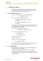
Страница 18: ... specification Alternatively you can measure it using a voltmeter For a pulsed output the heat output is given by Heat output IO x duty cycle x VS VL Where IO Output current set by the user VS Supply voltage VL Voltage across the light And duty cycle is defined as Duty cycle WP x FT Where WP Pulse width in seconds FT Trigger frequency in Hz When overdriving the voltage across the light is more dif...

Страница 19: ...s or LEDs in parallel then changing the arrangement to serial will increase the voltage across them but reduce the overall current Use a higher power controller from the Gardasoft range for example a PP820 can dissipate much more heat With no heatsinking and no airflow the PP500 can dissipate the following 8W at 25 C ambient 4W at 40 C ambient If the heat output is no greater than 8W no heatsinkin...

Страница 20: ...lowing connections Screw terminal ID Function TRIG1 Channel 1 trigger input TRIG1 LED1 Channel 1 lighting output LED1 PSU Power supply PSU Power supply LED2 Channel 2 lighting output LED2 TRIG2 Channel 2 trigger input TRIG2 8 1 Triggers The PP500 triggers are opto coupled as shown in the circuit below A VTRIG voltage between 3V to 24V provides a logic 1 and any VTRIG voltage 20 WWW STEMMER IMAGING...

Страница 21: ...ned to pass at their rated current while in the USA fuses are designed to blow at their rated current 8 3 Wiring Refer to Section 2 2 Electrical or Section 3 2 Elektrik or Section 4 2 Électricité for important guidance on wiring up your PP500 Ensure that the wire gauge used for these connections is appropriate for the current to be drawn Ideally wires should be double crimped or independently secu...

Страница 22: ...ready for operation To show the unit is operating normally the LED display shows a pattern of alternating lines 9 2 Setting the light rating The Autosense feature detects the presence of a light and prompts you to set the rating as follows When the PP500 detects a light connected to channel 1 for the first time Sn1 is displayed A light connected to channel 2 will display Sn2 When the Cu1 prompt is...

Страница 23: ...displays are shown for channel 2 connected and channels 1 and 2 connected If an error occurs if the light is disconnected for example the PP500 displays OP Press the SEL button to cancel this 9 3 Setting up continuous output Press the SEL button for 1 second and follow the steps below CH1 is displayed Use the p and q buttons to select CH2 if you wish to set up channel 2 Press the SEL button 23 WWW...

Страница 24: ... the SEL button Use the p and q buttons to set the intensity from 1 to 99 9 and press the SEL button Your PP500 is ready to use 9 4 Setting up switched output Press the SEL button for 1 second and follow the steps below CH1 is displayed Use the p and q buttons to select CH2 if you wish to set up channel 2 Press the SEL button 24 WWW STEMMER IMAGING COM ...

Страница 25: ...on Use the p and q buttons to set the intensity from 1 to 99 9 and press the SEL button Your PP500 is ready to use 9 5 Setting up pulsed operation Press the SEL button for 1 second and follow the steps below CH1 is displayed Use the p and q buttons to select CH2 if you wish to set up channel 2 Press the SEL button 25 WWW STEMMER IMAGING COM ...

Страница 26: ...Use the p and q buttons to set the intensity from 1 to 999 and press the SEL button deL is displayed Press the SEL button to set up the delay time as described in Section 9 6 Setting pulse delay and width times PUL is displayed Press the SEL button to set up the pulse width time as described in Section 9 6 Setting pulse delay and width times 26 WWW STEMMER IMAGING COM ...

Страница 27: ...at Range of values E 3 0 001 999 Values displayed in milliseconds from 1ms to 999ms in steps of 1ms E 4 0 0001 99 9 Values displayed in milliseconds from 0 1ms to 99 9ms in steps of 0 1ms E 5 0 00001 9 99 Values displayed in milliseconds PP500 0 02ms to 980ms in steps of 0 02ms PP500F 0 01ms to 9 99ms in steps of 0 01ms E 6 0 000001 999 Values displayed in microseconds PP500 20μs to 980μs in steps...

Страница 28: ... to 99 9ms in steps of 0 1ms Press the SEL button Use the p and q buttons to select the desired value Press the SEL button Use the p and q buttons to select E 5 to enter values from 0 02ms to 9 98ms in steps of 0 02ms using a PP500 or 0 01ms to 9 99ms in steps of 0 01ms using a PP500F Press the SEL button Use the p and q buttons to select the desired value Press the SEL button 28 WWW STEMMER IMAGI...

Страница 29: ...0μs in steps of 20μs using a PP500 or 1μs to 999μs in steps of 1μs using a PP500F Press the SEL button Use the p and q buttons to select the desired value Press the SEL button Note When a light is pulsed the PP500 shows that a trigger has occurred by displaying PUL in the display window 29 WWW STEMMER IMAGING COM ...

Страница 30: ...urrent is lower at 24V Input enable level From 3V to 24V This is the voltage applied between and of each input Input disable level 1V See above Typical trigger input current 3mA at 3V to 24V Max output current per channel 2A continuous 10A pulsed Maximum total average output current 2A The average current for all channels added together must not exceed this Ambient temperature during operation 5 C...

Страница 31: ...creased too much Check for ageing of the lighting or a failed LED LO The voltage required for the lighting has decreased too much Check for ageing of the lighting or a failed LED FAt Fatal The PP500 is too hot The PP500 is fitted with a thermal cut out If the internal temperature reaches 62 C corresponding to a case temperature of 70 C the outputs are turned off This message is displayed until the...

Страница 32: ...rinity Court Buckingway Business Park Cambridge CB24 4UQ UK tel 44 1954 234970 fax 44 1954 231567 Gardasoft LLC Oak Ridge Road Weare New Hampshire 03281 USA tel 1 603 657 9026 www gardasoft com WWW STEMMER IMAGING COM ILL GARD29 10 2019 Subject to technical change without notice No liability is accepted for errors which may be contained in this document ...

Отзывы: