background image

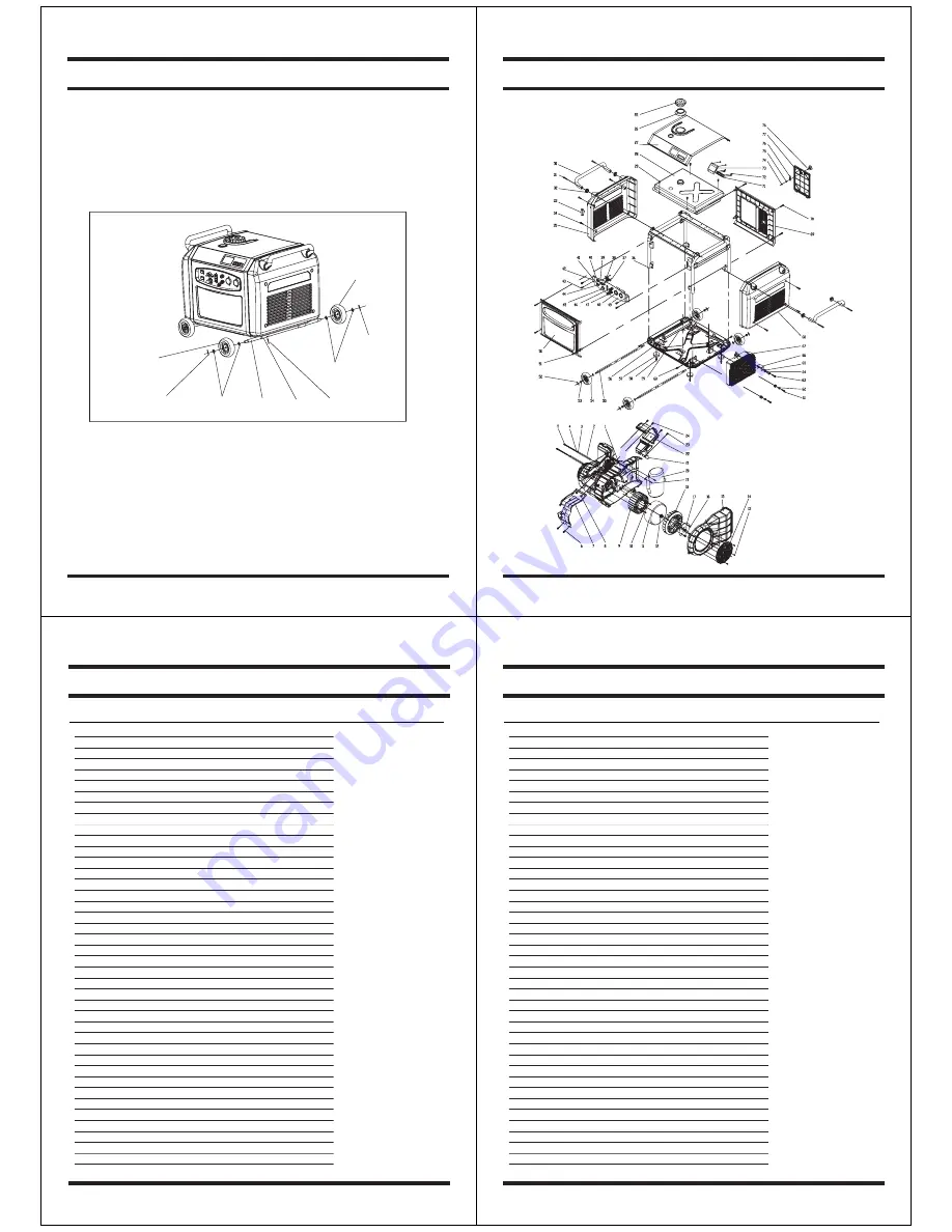
12.WHEEL KIT

The unit comes with the rubber pad already installed. If you wish to install the wheel kit, please
perform the following procedure: 

a. Insert the axle into sleeves welded in the bottom of the chassis.
b. Insert the lock pin through the hole in the sleeve and the axle.
c. Install the washer, wheel, washer, and lock pin in order at one end of the axle, then repeat

it until all wheels are installed.

Lock pin

Fig.22

Washer

Wheel

Axle

Sleeve

Washer

Lock pin

Wheel

Lock pin

Owner’s Manual

28

29

3500W Digital Generator

APA 

Part 

No. 

 Description 

  Part 

No.

APG3104-01-BOLD 

 Engine

   01

APG3104-02-BOLD 

 Liner 

tube 

   02

APG3104-03-BOLD 

 Washer 

   03

APG3104-04-BOLD 

 Filling 

piece   04

APG3104-05-BOLD 

 Bolt 

   05

APG3104-06-BOLD 

 Bolt 

   06

APG3104-07-BOLD 


Upper ventilation cover 


07

APG3104-08-BOLD 

 Nut 

   08

APG3104-09-BOLD 

 Stator 

   09

APG3104-10-BOLD 

 Bolt 

   10

APG3104-11-BOLD 

 Rotor 

   11

APG3104-12-BOLD 

 Nut 

   12

APG3104-13-BOLD 

 Bolt 

   13

APG3104-14-BOLD 

 Magneto 

shield 

  14

APG3104-15-BOLD 

 Magneto 

cover 

  15

APG3104-16-BOLD 

 Bolt 

   16

APG3104-17-BOLD 

 Depressor 

   17

APG3104-18-BOLD 

 Fan 

   18

APG3104-19-BOLD 

 Bolt 

   19

APG3104-20-BOLD 

 Muffler 

   20

APG3104-21-BOLD 


Lower ventilation cover 


21

APG3104-22-BOLD 


Cylinder head ventilation cover 


22

APG3104-23-BOLD 

 Bolt 

   23

APG3104-24-BOLD 

 Bolt 

   24

APG3104-25-BOLD 

 Fuel 

tank 

cover 

  25

APG3104-26-BOLD 

 Sealing 

ring   26

APG3104-27-BOLD 

 Top 

cover 

   27

APG3104-28-BOLD 

 Fuel 

tank 

   28

APG3104-29-BOLD 

 Bolt 

   29

APG3104-30-BOLD 

 Handle 

   30

APG3104-31-BOLD 

 Bolt 

   31

APG3104-32-BOLD 

 Sealing 

ring   32

APG3104-33-BOLD 

 Start 

grip 

   33

APG3104-34-BOLD 

 Bolt 

   34

APG3104-35-BOLD 

 Ring 

cover 

   35

APG3104-36-BOLD 

 Frame 

   36

APG3104-37-BOLD 

 Bolt 

   37

APG3104-38-BOLD 

 Fuel 

switch 

   38

APG3104-39-BOLD 

 Oil 

alert 

lamp 

  39

APG3104-40-BOLD 

 Engine 

switch 

  40

Owner’s Manual

30

APA 

Part 

No. 

 Description 

  Part 

No.

APG3104-41-BOLD 

 Econ 

switch   41

APG3104-42-BOLD 

 Control 

panel 

  42

APG3104-43-BOLD 

 Bolt 

   43

APG3104-44-BOLD 

 Fuel 

valve 

lever 

  44

APG3104-45-BOLD 

 Cabel 

   45

APG3104-46-BOLD 

 Indicator 

   46

APG3104-47-BOLD 

 DC 

terminal   47

APG3104-48-BOLD 

 AC 

receptacle 

  48

APG3104-49-BOLD 

 Control 

panel 

film 

  49

APG3104-50-BOLD 

 Front 

cover 

   50

APG3104-51-BOLD 

 Bolt 

   51

APG3104-52-BOLD 

 Lock 

pin 

   52

APG3104-53-BOLD 

 Washer 

   53

APG3104-54-BOLD 

 Wheel 

   54

APG3104-55-BOLD 

 Axle 

   55

APG3104-56-BOLD 

 Shock 

absorber 

  56

APG3104-57-BOLD 

 Rubber 

pad   57

APG3104-58-BOLD 

 Bolt 

   58

APG3104-59-BOLD 

 Cubic 

tube 

   59

APG3104-60-BOLD 

 Bolt 

   60

APG3104-61-BOLD 

 Bolt 

   61

APG3104-62-BOLD 

 Lower 

liner 

tube 

  62

APG3104-63-BOLD 

 Bolt 

   63

APG3104-64-BOLD 

 Upper 

liner 

tube 

  64

APG3104-65-BOLD 

 Rubber 

mat   65

APG3104-66-BOLD 

 Stand 

   66

APG3104-67-BOLD 

 Module 

   67

APG3104-68-BOLD 

 Left 

cover 

   68

APG3104-69-BOLD 

 Rear 

cover 

   69

APG3104-70-BOLD 

 Bolt 

   70

APG3104-71-BOLD 

 Operation 

button 

  71

APG3104-72-BOLD 

 Bolt 

   72

APG3104-73-BOLD 

 LCM 

   73

APG3104-74-BOLD 

 Nut 

   74

APG3104-75-BOLD 

 Washer 

   75

APG3104-76-BOLD 

 Lock 

sheet 

   76

APG3104-77-BOLD 

 Access 

door   77

APG3104-78-BOLD 

 Knob 

   78


3500W Digital Generator

31

Содержание SP-GG350D

Страница 1: ...onsult an authorized dealer 3500W Digital Generator 1 Our generators are designed to give safe and dependable service if operated according to instructions Read and understand the Owner s Manual before operating the generator Failure to do so could result in personal injury or equipment damage CONTENTS 1 SAFETY INSTRUCTIONS 3 2 SAFETY LABEL LOCATIONS 5 3 PRE OPERATION CHECK 8 4 STARTING THE ENGINE...

Страница 2: ...arter grip Control panel Fuel filler cap Air intake hole Front cover LCD screen Operation button Side cover 3500W Digital Generator 5 2 2 Control pannel Fig 2 Control panel ON Engine speed is kept at economical state automatically to minimize the fuel consumption while in operation This position is recommended when the output power is less than 1 kW 2 3 ECON switch When high electrical load applia...

Страница 3: ... refueling tighten the fuel filler cap securely Fig 5 Oil surface E F Loosen Tighten 3500W Digital Generator 9 Gasoline containing alcohol If you decide to use a gasoline containing alcohol gasohol be sure its octance rating is at least as high as being recommended by us There are two types of gasohol one containing ethanol and the other containing methanol Do not use gasohol that contains more th...

Страница 4: ...during a power outage and when utility power is restored the generator may explode burn or cause fires in the building s electrical system Limit operation requiring maximum power to 30 minutes For continuous operation do not exceed the rated power In either case the total wattage of all appliances connected must be considered Do not modify or use the generator for other purposes than it is intende...

Страница 5: ...tal Generator 17 7 MAINTENANCE The purpose of the maintenance and adjustment schedule is to keep the generator in the best operating condition Shut off the engine before performing any maintenance If the engine must be run make sure the area is well ventilated The exhaust contains poisonous gases Use our genuine parts or the equivalent The use of replacement parts which are not of equivalent quali...

Страница 6: ...cover and tighten the cover screw 10 Close the access door Plug gap The spark plug must be securely tightened An improperly tightened spark plug can become very hot and possibly damage the generator Never use a spark plug with an improper heat range 3500W Digital Generator 21 7 5 Spark arrester maintenance If the generator has been running the muffler will be very hot Allow it to cool before proce...

Страница 7: ...cuit Switch on the DC output Replace the DC circuit fuse Take the generator to an authorized dealer NO YES NO Is the operation indicator light ON Is the short circuit indicator light ON Check the electrical appliance or equipment for any defects Take the generator to an authorized dealer Take the generator to an authorized dealer Replace the electrical appliance or equipment Take the electrical ap...

Страница 8: ...r 27 APG3104 28 BOLD Fuel tank 28 APG3104 29 BOLD Bolt 29 APG3104 30 BOLD Handle 30 APG3104 31 BOLD Bolt 31 APG3104 32 BOLD Sealing ring 32 APG3104 33 BOLD Start grip 33 APG3104 34 BOLD Bolt 34 APG3104 35 BOLD Ring cover 35 APG3104 36 BOLD Frame 36 APG3104 37 BOLD Bolt 37 APG3104 38 BOLD Fuel switch 38 APG3104 39 BOLD Oil alert lamp 39 APG3104 40 BOLD Engine switch 40 Owner s Manual 30 APA Part No...

Страница 9: ...t costs if any must be paid by the purchaser If the purchaser does not receive satisfactory results form the Authorized Warranty Service Center the purchaser should contact Steele toll free 888 896 6881 THIS WARRANTY DOES NOT COVER Merchandise sold as reconditioned used as rental equipment or floor or display models Merchandise that has become damaged or inoperative because of ordinary wear misuse...

Отзывы: