background image

Startco Engineering Ltd.

Page 3

SE-701 Ground-Fault Monitor


Rev. 5

Pub. SE-701-M, December 14, 2006.

If Switch 5 is in the LATCHING position, a trip

remains latched until the RESET switch is pressed, the
remote-reset terminals are momentarily shorted, or the
supply voltage is cycled.  Cycling the supply voltage will
not reset (black) the fluorescent flag.

If Switch 5 is in the AUTORESET position, a trip will

reset when the fault is removed.  The fluorescent flag will
not reset until the RESET switch is pressed or the remote-
reset terminals are momentarily shorted.  Cycling the
supply voltage will not reset the fluorescent flag unless
the remote-reset terminals are shorted.

2.2.4  T

EST

The TEST switch is used to test the ground-fault

circuit, the indication, and the output relay.  When the
TEST switch is pressed for one second; the circuit will
trip, trip indication will come on, and the output relay will
operate.  If high-current inhibit has been selected, the
inhibit indicator will come on.

2.3  F

RONT

-P

ANEL

 I

NDICATION

2.3.1  P

OWER

The green LED labeled PWR indicates the presence of

supply voltage.

2.3.2  G

ROUND

-F

AULT

 T

RIP

The red LED and the fluorescent flag, labeled TRIP,

indicate a trip.  A solid red LED indicates a ground-fault
trip and a flashing LED indicates a trip initiated by a CT
fault.

2.3.3  I

NHIBIT

The yellow LED labeled INHB indicates that output-

relay operation was inhibited during a high-current

ground fault.  When a ground-fault trip occurs, both the
TRIP and INHB LED’s will be ON.  Inhibit indication is
reset when the ground-fault trip is reset.  Inhibit operation
and indication will not respond if Switch 2 is in the
INHIBIT OFF position.

2.4  A

NALOG

 O

UTPUT

The non-isolated, 0- to 5-V analog output indicates

ground-fault current sensed by the ground-fault CT.  The
output is 5 V at 100% of the CT-primary rating.

3.  I

NSTALLATION

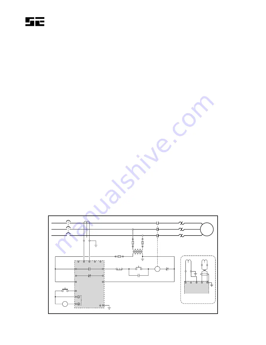
An SE-701 can be surface- or DIN-Rail-mounted.  See

Fig. 1.  Panel mounting requires a PMA-55 Panel-Mount
Adapter.  See Fig. 6.

Pass the phase conductors through the CT window as

shown in Fig. 2 (for 4-wire and single-phase systems, also
pass the neutral conductor through the CT window).  Do
not pass ground conductors through the CT window.  In
applications that require shields or drain wires to pass
through the CT window, return them through the CT
window before connecting them to ground.  If a ground
fault CT with a 5-A secondary is used, connect it to
terminals 2 and 3 (terminals 1 and 3 with a 1-A
secondary) and ground terminal 3.  If an EFCT-x is used,
connect it to terminals 4 and 5, connect the shield to
terminal 5, and ground terminal 

5.  Remove the

connection to terminal 9 for dielectric-strength testing
—all inputs and outputs have ANSI/IEEE C37.90 surge-
protection circuits that conduct above 300 Vac.  See
Figs. 3, 4, and 5 for sensitive EFCT-x dimensional
drawings.

XX

5

X:

1 A 5 A

C

STOP

START

1M

1M

SE-701

RS

REMOTE RESET

V

LEAKAGE

ANALOG
OUTPUT

S1

S2

O/L

L

N

1

2

4

3

5

13

14

15

16

6

7

8

9

L1

11

10

L2

ISOLATED CONTACTS

1 A 5 A

C

S1 S2

1

2

3

4

5

SE-701

EFCT-X

ALTERNATE CT
CONNECTIONS

XXX:1

OR

Technical Information 11.1
provides additional
information on CT selection.

                        FIGURE 2.  Typical Connection Diagram.

Содержание SE-701

Страница 1: ...SE 701 MANUAL GROUND FAULT MONITOR December 14 2006 Revision 5 Copyright 2006 by Startco Engineering Ltd All rights reserved Publication SE 701 M Document S95 C701 00000 Printed in Canada ...

Страница 2: ...rip 3 2 3 3 Inhibit 3 2 4 Analog Output 3 3 Installation 3 4 Technical Specifications 8 5 Ordering Information 9 6 Warranty 9 7 Ground Fault Performance Test 10 LIST OF FIGURES PAGE 1 SE 701 Outline and Mounting Details 2 2 Typical Connection Diagram 3 3 EFCT 1 Outline and Mounting Details 4 4 EFCT 2 Outline and Mounting Details 5 5 EFCT 26 Outline and Mounting Details 6 6 PMA 55 Panel Mount Adapt...

Страница 3: ...operate in applications where the ground fault current can be larger than the interrupting capacity of the device tripped by the SE 701 2 1 3 CT VERIFICATION Switch 3 is used to enable CT verification with an EFCT series CT In the CT VERIFY ON position a trip will occur if the CT is disconnected The red TRIP LED will flash to indicate a trip initiated by a CT fault Switch 3 must be in the CT VERIF...

Страница 4: ...Startco Engineering Ltd Page 2 SE 701 Ground Fault Monitor Rev 4 Pub SE 701 M December 14 2006 FIGURE 1 SE 701 Outline and Mounting Details ...

Страница 5: ... INHB LED s will be ON Inhibit indication is reset when the ground fault trip is reset Inhibit operation and indication will not respond if Switch 2 is in the INHIBIT OFF position 2 4 ANALOG OUTPUT The non isolated 0 to 5 V analog output indicates ground fault current sensed by the ground fault CT The output is 5 V at 100 of the CT primary rating 3 INSTALLATION An SE 701 can be surface or DIN Rail...

Страница 6: ...0 121 0 80 0 30 0 20 5 30 0 138 0 MAX 126 0 56 0 46 0 4 76 0 98 4 33 0 22 0 22 0 87 3 23 2 75 2 21 4 76 3 15 1 18 0 81 1 18 5 43 4 96 2 21 1 81 M5 SCREWS TOP MOUNTING DETAIL NOTE 2 FRONT SIDE 5 0 0 20 0 FLUX CONDITIONER OPTIONAL RECESSED FOR 8 mm HEX NUT 1 0 0 04 DEEP EFCT 1 EARTH FAULT CT 600 V INSULATION CLASS STARTCO E N G I N E E R I N G L T D P P S S 2 2 1 1 FIGURE 3 EFCT 1 Outline and Mounti...

Страница 7: ... 0 33 2 06 2 36 2 52 1 22 9 29 M5 SCREWS TOP MOUNTING DETAIL M4 OR 8 32 TAP SIDE FRONT E F C T 2 E A R T H F A U L T C T 6 0 0 V I N S U L A T I O N C L A S S S T A R T C O E N G I N E E R I N G L T D 5 0 0 20 DIA NOTES 1 DIMENSIONS IN MILLIMETRES INCHES MOUNTING SCREWS M4 OR 8 32 2 P P S S2 2 1 1 S P 1 1 139 7 5 50 BONDING SCREW FLUX CONDITIONER INCLUDED 26 5 1 04 FIGURE 4 EFCT 2 Outline and Moun...

Страница 8: ...NTING SCREWS M4 OR 8 32 68 0 26 0 52 5 5 0 5 0 68 0 34 0 26 5 25 0 58 0 17 0 26 5 72 0 34 0 7 0 110 0 MAX 52 5 42 6 2 68 1 02 2 07 0 20 0 20 2 68 1 34 1 04 0 98 2 28 0 67 1 04 2 83 1 34 0 87 0 43 2 07 1 68 M5 SCREWS TOP MOUNTING DETAIL M4 OR 8 32 TAP FRONT SIDE 4 0 0 16 0 RECESSED FOR 7 mm HEX NUT 3 0 0 12 DEEP P P S S 2 2 1 1 EFCT 26 EARTH FAULT CT 600 V INSULATION CLASS STARTCO E N G I N E E R I...

Страница 9: ...Startco Engineering Ltd Page 7 SE 701 Ground Fault Monitor Rev 5 Pub SE 701 M December 14 2006 FIGURE 6 PMA 55 Panel Mount Adapter ...

Страница 10: ... On Class II Level 11 x CT Primary Rating Input Algorithms DFT Digital or Peak Digital Filter 50 to 60 Hz Bandpass CT 1 or 5 A Secondary Rating or EFCT x CT Detection Open Circuit Detection with EFCT x Thermal Withstand Continuous 5 x CT Secondary Rating 1 Second 80 x CT Secondary Rating Burden 5 A input 0 01 Ω 1 A input 0 05 Ω EFCT input 2 Ω Analog Output Range 0 to 5 Vdc 5 V 100 CT Rating Output...

Страница 11: ...y rating 82 mm 3 2 window EFCT 1FC Flux Conditioner for EFCT 1 70 mm 2 7 window EFCT 2 Sensitive Earth Fault CT with Flux Conditioner 5 A primary rating 139 mm 5 5 window EFCT 26 Sensitive Earth Fault CT 5 A primary rating 26 mm 1 window PMA 55 Panel Mount Adapter SE EFVC Voltage Clamp Consult factory for custom mounting adapters 6 WARRANTY The SE 701 Ground Fault Monitor is warranted to be free f...

Страница 12: ...determine the existence of alternate ground paths d Verify proper reaction of the circuit interrupting device in response to a simulated or controlled ground fault current To simulate ground fault current use CT primary current injection Fig 7 a shows a test circuit using a Startco SE 400 Ground Fault Relay Test Unit The SE 400 has a programmable output of 0 5 to 9 9 A for a duration of 0 1 to 9 9...

Отзывы: