Starke Arvid AB Tel: +46 522 - 22 000 Fax: +46 522 - 22 344
Lyckåsvägen 3
www.starkearvid.se [email protected]e
SE-459 30 Ljungskile
Sida
22
av
25
Leak check
Leak check for the entire system
You can perform a leak check of the two independently functioning vacuum circuits to find
the leak as follows.
First of all, you should check the entire vacuum circuits with all suckers and the hose lines
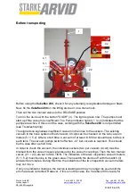
to the two vacuum circuits. To do so, the two manual valves should be set to SUCTION.
Furthermore, it is necessary to set all suckers on a gas-impermeable, flat material (for ex-
ample, a metal or glass sheet) that can be sucked up. Then the vacuum pumps are
switched on and when the maximum achievable vacuum, as a rule approx. -0.7 bar in
each vacuum circuit is achieved, the pumps are switched off. Read the achieved vacuum
from the vacuum meters and record the value in writing. The indicators of the vacuum me-
ters should only change slightly within the next fifteen minutes, not more than 5%. If the
result of this test is positive, the vacuum lifting device is tight and you can work with it
without risk. If a leak is detected even in one vacuum circuit, so the device will not function
and may not be put into operation.
The leak must be corrected immediately or the porous material replaced.
Leak check without suckers
If the result of the test of the entire circuit is negative, the next step is to check the vacuum
reserve tanks with the supply lines to the vacuum couplings of the individual suckers (two
per vacuum circuit). To do so, set the manual valves (2.1 / 2.2) to SUCTION and block the
hose line to the vacuum couplings. Then switch the vacuum pumps on and continue with
the leak test as described above. If this test runs positively, it is tight from the vessel areas
to the individual vacuum couplings and the error must be in the individual suckers. Con-
nect one sucker after the other and test each one in the same way. To do this, the sucker
must be sealed with a gas-impermeable material. This procedure determines the defective
area exactly and the error can be corrected quickly by replacement.
Attention!
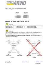
- Blue hose line
=
vacuum circuit1
=
vacuum coupling blue
- Black hose line =
vacuum circuit2
=
vacuum coupling black
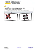
Attention!
The suction pads on the device must always be attached in such a way that vacuum cir-
cuit 1 and vacuum circuit 2 are connected in every suction row see (A).
The suction pads must never be attached in such a way that only one vacuum circuit is
connected in suction row (B).

