4
IL1173
A
B
C
D
E
F
G
H
H
I
J
VIEW
A
VIEW
A
K
L
M
N
O
I
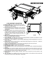
OVEN COMPONETS DESCRIPTION
A: Conveyor Belt:
Moves the product through the oven
B: Conveyor Assembly:
Supports the Conveyor Belt, the
ends fold up for easy removal.
C: Control Panel:
Bright Red Display for easy noti
fi
cation
of ovens current operation, and buttons for making quick
modi
fi
cations.
D: Air Intake:
Located on the end of the control box to pre-
vent the electronic controls from overheating as well as
to allow for a more direct air
fl
ow into the blowers. DO
NOT BLOCK these air intakes and wipe them clean on a
regular basis.
E: Machinery Compartment Access Door:
Allows access
to the oven’s interior Finger components.
F: Access Window:
This allows easy access to the cooking chamber, for product to be placed in to give
a shorter or additional cooking time to the product.
G: Heat Shutter:
Can be adjusted to various settings, depending on product being placed in the oven, to
prevent heat loss
H: Crumb Tray:
Catches crumbs and other material that drops through the conveyor belt. Located at
each end of the conveyor assembly.
I: Conveyor End & Side Stops:
Prevents product from falling off of the moving conveyor.
J: Fingers:
Projects streams of hot air onto the product.
K: Circuit Breaker 10Amp:
Protects components from over amperage.
L: Hi-Limit Reset:
Monitors inside cooking temperature and will only trip when unitended temperature is
reached.
M: Nameplate:
Has speci
fi
c information regaring this units electrical & gas requirements as well as the
units serial number which is needed for any service that will be required. This number should be written
in the inside cover of this manual and kept for future needs
N: Electrical Input:
Electrical Supply connection must meet all national and local electrical code
requiremtns.
O: Gas Connection:
The installation must con
fi
rm with local codes or in the absence of local codes, with
the National Fuel Gas Code, ANSI Z2223.1 latest edition.
OVEN COMPONENTS
Содержание Ultra-max UM3240
Страница 27: ......


