Page 3
1.
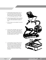
Use a 1/4” allen key to install the left side rail
(701-0002-XX) to the frame using three (3) pieces
each of the 5/16” x 1” socket head cap screw
(110-3416), 5/16” split lock washer (120-0496),
and 5/16” fl at washer (120-0490). Once the
handrail is installed, slide the left side handrail
grommet (020-7528) onto the rail -
be careful of
orientation of the grommet.
2.
Repeat Step 1 for the right side rail (701-0003-XX)
and rail grommet (020-7527).
DO NOT FULLY TIGHTEN
3.
Use a 1/4” allen key to install the mast (715-4034-
XX) to the frame using two (2) pieces each of the
5/16” x 1” and 5/16” x 3” (110-3126
)
socket head
cap screws, and four (4) pieces each of the 5/16”
split lock washer and 5/16” fl at washer.
DO NOT FULLY TIGHTEN
4.
Ensure that the supplementary power cable is
connected to the J20 port on the MCB and the
main data cable is connected to the J1 port on
the MCB.
J20 -
Supplementary
Power
J1 -
Main
Data
Cable
5.
Install the mast beauty ring (715-4032-XX) onto
the mast, ensure that the tab on the ring is facing
in towards the rear of the unit.
6.
Install one (1) rail beauty ring (715-4031-XX)
onto both the left and right rails. Ensure that the
small cutout on the bottom of the ring is facing
forward to the front of the machine.


