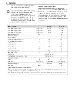
the hose nozzle.
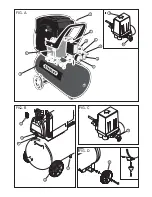
14. Oil Drain Plug.-
Allows the removal of lubricant oil.
15. Oil Gauge Dipstick.-
Shows the oil level and allows its
replacement.
16. Identification Tag/Information Sticker.-
Shows the
compressor’s technical data.
17. Tank’s Identification Tag.-
Shows the tank’s technical data.
18. Wire with Plug (2P+GR).-
Used to connect the
compressor to the electric supply.
19. On/Off Button.-
Starts/Shuts off the compressor.
20. Rubber Feet.-
Used for the support of the compressor set.
21. Wheels.-
Help to move the compressor.
22. Hose Nozzle.-
Used to connect the hose to the
compressor, to accessories or hose nozzle (not shown).
Safety Devices (Fig. C)
Safety Valve
The spring safety valve
(10)
is incorporated into the pressure
switch unit. The safety valve opens if the max. permissible
pressure is exceeded.
OPERATION
Prior to Initial Operation
Install Wheels (Fig. D)
1.
Install wheels
(15)
as illustrated.
2.
Install rubber feet as illustrated.
Insert Dip Stick (Fig. E)
1.
Remove the plug
(12)
from the crankcase.
2.
Substitute the plug with the dip stick
(14)
supplied.
The plug prevents oil from leaking from the crankcase during
shipping. Keep plug for future use.
Install Air Intake Filter
(Fig. F)
.
1.
Remove plug from air intake of compressor pump housing.
Keep plug for future use.
2.
Screw air filter
(1)
supplied on air intake.
Check Condensate Drain (Fig. G)
► Check to see that the condensate drain's screw
(11)
is closed.
INSTALLATION OF THE AIR NETWORK
1. Assembly:
Remove the product from the packaging and
rubber feet
.
2. Location:
Install the compressor in a covered, well ventilated
area, free of dust, gases, toxic gases, humidity or any other
kind of pollution. The ambient temperature recommended
during work is: minimum of 5°C (41°F) and maximum of
40°C (104°F). In order to avoid damage to the compressor,
operate it on a level foundation.
2.1 Compressor’s Installation:
When this compressor
model is coupled to a compressed air network, the
connection must be made by a hose or expandable
joints so that the charges, thermal expansion, piping’s
weight, mechanical and thermal shocks or obstructions
are not transmitted to the air receiver. The air receiver
may be damaged if these warnings are not observed.
3. Position:
Keep a minimum distance of 800 mm (32") from
any obstacle, to allow good ventilation during operation and
to make maintenance easier.
4. Quality of Compressed Air:
For services in which the air
must be free of oil or dust particles, the installation of
special
air filters. Please contact the nearest
StanleyBlack&Decker
Authorized Service Center for information.
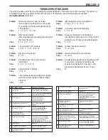
5. Electrical Connection:
5.1
Look for a specialized technician to evaluate
the electrical supply and to select the adequate protection
and input devices
Electrical Wiring Diagram.
Electrical Wiring Diagram
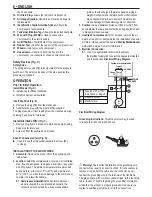
Grounding Instructions:
This product must be grounded
to reduce the risk of an electric shock.
Warning!
The incorrect installation of the grounding wire
connector may result in an electric shock. If it is necessary to
replace or repair both the cable and the connector, do not
connect the grounding wire to the terminal of the flat blade.
The green cable, with or without yellow stripes, is the rounding
cable. In case of doubts regarding the grounding information
or whether the product is properly grounded, make sure you
contact a qualified electrician to verify the connections.
6
• ENGLISH
P
F1
TERRA
Tensão de
Alimentação
PLUG 2P+T
OU CA BO
ELÉTRICO
Responsabilidade do cliente
M
1~
Fase
N
Neutro
P
F1
GROUND
Tension
Supplies
GR
OR WIRE
Customer's responsibility
M
1~
Phase
N
Neutral
P
F1
TIERRA
Tensión de
alimentación
PLUG 2P+T
O CORDÓN
Responsabilidad del cliente
M
1~
Fase
N
Neutro
P
F1
TERRA
Tensão de
Alimentação
PLUG 2P+T
OU CA BO
ELÉTRICO
Responsabilidade do cliente
M
1~
Fase
N
Neutro
P
F1
GROUND
Tension
Supplies
GR
OR WIRE
Customer's responsibility
M
1~
Phase
N
Neutral
P
F1
TIERRA
Tensión de
alimentación
PLUG 2P+T
O CORDÓN
Responsabilidad del cliente
M
1~
Fase
N
Neutro
F1 Fuse type "D" or "NH"
(See Table 2 - Page 5)
P Pressure switch
M Electric motor
ENCHUFE CON
ATERRAMENTO
ENCHUFE CON ATERRAMENTO
ENCHUFE
A TIERRA
ESPIGA
A TIERRA
ESPIGAS DE
ATERRAMENTO
ESPIGAS DE ATERRAMENTO
GROUNDED
OUTLET
GROUNDED OUTLET
GROUNDED
OUTLET
GROUNDING
PIN
GROUNDING
PIN
GROUNDING PIN
TOMADA COM
CONEXÃO DE
ATERRAMENTO
PINO DE
ATERRAMENTO
ENCHUFE CON
ATERRAMENTO
ENCHUFE CON ATERRAMENTO
ENCHUFE
A TIERRA
ESPIGA
A TIERRA
ESPIGAS DE
ATERRAMENTO
ESPIGAS DE ATERRAMENTO
GROUNDED
OUTLET
GROUNDED OUTLET
GROUNDED
OUTLET
GROUNDING
PIN
GROUNDING
PIN
GROUNDING PIN
TOMADA COM
CONEXÃO DE
ATERRAMENTO
PINO DE
ATERRAMENTO

