17
SERVICE
PRIOR TO DISASSEMBLY
Note:
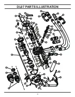
For orientation of parts in the following procedures,
refer to the parts drawing later in this manual
1. Clean the exterior of the tool and place on a clean work
surface.
2. Obtain the seal kit listed on the PARTS LIST so all seals
exposed during disassembly can be replaced.
PRIOR TO REASSEMBLY
1. Clean all parts with a degreasing solution.
2. Blow dry all parts or use lint-free cloths.
3. Ensure that all seals exposed during disassembly are
replaced with new parts.
4. Apply clean grease or o-ring lubricant to all parts during
assembly.
TOOL DISASSEMBLY
GEAR HOUSING
1. Remove the chuck (33) from the output shaft (36) by
holding the seal nut (35) with an open end wrench and turn-
ing the chuck counter-clockwise.
2. Remove the capscrews (31) and lockwashers (32) se-
curing the gear housing (69) to the main housing assembly
(76). If the tool has a trigger guard (80), remove capscrew
(34), nut (20) and trigger guard before removing the gear
housing.
3. Remove the ring gear (27), roll pin (5) and gasket (71).
4. Remove the retaining ring (29) near the planet shafts
(23) before removing the planet shafts. Remove the seal
nut (35) by using the planet shaft holes to keep the output
shaft from turning. Pull the output shaft with attached parts
from the gear housing.
5. Remove the planet gears (26) from the output shaft.
Inspect shafts, gears and gear bore bushings (see CLEAN-
ING AND INSPECTION procedure).
6. Spin the ball bearing (28) on the output shaft. The bear-
ing should turn smoothly. To replace the bearing, support
the outer race and press down on the output shaft from the
chuck end. Do not reuse the ball bearing once it has been
removed from the output shaft.
7. Remove the output shaft seal (30) by pressing it from
the gear housing bore.
8. Check the end faces of the seal nut and output shaft for
nicks and war (see CLEANING AND INSPECTION proce-
dure).
MOTOR CAP
9. Remove the six capscrews (41) and lockwashers (3)
securing the motor cap assembly (46) to the main housing
assembly and lift off the motor cap assembly. Do not in any
way excessively force the motor cap off the main housing
assembly.
10. Remove the o-ring (9) from the motor cap.
MAIN SHAFT AND IDLER SHAFT
11. Tap on the small gear end of the main shaft (5) and
push the shaft from the main body.
12. Remove the idler gear (45) and idler shaft (47).
13. Remove the retaining ring (16) and then pick out the
seal washer (44), back-up ring (39) and o-ring (4) from the
main housing.
VALVE SPOOL
14. Unscrew the spring cap (66), pick out the spring (79)
and push the valve spool (59) out the spring cap end of the
main housing.
TRIGGER
15. Remove the trigger by fi rst removing the capscrews (8)
and lockwashers (32) and removing the trigger and trigger
mount (78) as an assembly. Drive out the roll pin (21).
REVERSING SPOOL
16. Remove the retaining rings (67) and end caps (65).
17. Unscrew the seal caps (64) and slide the reversing
spool (68) out of the main housing. Make sure the idler
shaft has been removed prior to completing this step.
Содержание DL07
Страница 2: ......
Страница 20: ...20 DL07 PARTS ILLUSTRATION ...

