11
OPERATION
PREOPERATION PROCEDURES
CHECK POWER SOURCE
1. Using a calibrated fl ow meter and pressure gauge, check
that the hydraulic power source develops a fl ow of 4-12
gpm/15-45 lpm at 1000-2000 psi/70-140 bar.
2. Make certain that the hydraulic power source is equipped
with a relief valve set to open at 2100 psi/145 bar minimum.
CONNECT HOSES
1. Wipe all hose couplers with a clean lint-free cloth before
making connections.
2. Connet hoses from the hydraulic power suupply to the
tool quick disconnects. It is good practice to connect the
return hose fi rst and disconnect it last to minimize or avoid
trapped pressure within the drill.
3. Observe the arrow on hose couplers to ensure that the
fl ow is in the proper direction. The male coupler on the
circtuit hose end is the supply (pressure) coupler.
4. Make sure the circuit PRESSURE (male quick disconect)
hose is conneced to the port at the back of the drill handle.
The circuit RETURN hose (female quick disconnect) is con-
nected to the port closest to the trigger.
5. Move the hyraulic circuit control valve to the ON position
to direct hydraulic fl ow to the drill.
Note:
If uncoupled hoses are left in the sun, pressure in-
crease inside the hose may result in making them dif-
fi cult to connect. Whenever possible, connect the free
ends of the hoses together.
OPEN-CENTER (OC) OR CLOSED-CENTER
(CC) OPERATION
The DL07 can be confi gured to run on OC or CC circuits.
1. Determine the system type.
2. Remove the hex plug (81) from the spring cap.
FOR OPEN-CENTER OPERATION:
Using a 3/16 in. hex, reach through the hole in the spring
cap and turn the selector screw counter-clockwise until
meeting resistance (from the retaining ring). Turn the selec-
tor clockwise and then counter-clockwise to be sure the
selector is being stopped by the retaining ring. Do not force
the selector screw. Open-center operation is now selected.
FOR CLOSED-CENTER OPERATION:
Using a 3/16 in. hex, reach through the hole in the spring
cap and turn the selector screw fully clockwise. When the
selector screw bottoms. Closed-center operation is now
selected.
To prevent damage to the retaining ring, do not attempt
to force the selector screw counter-clockwise beyond
the point of initial resistance.
Reinstall the hex plug. Failure to install the plug may intro-
duce contaminants to the spool bore resulting in replace-
ment of the valve spool and main housing.
DRILL OPERATION
1. Observe all safety precautions.
2. Place the selected drill bit fully into the chuck. Center the
bit and tighten the chuck using the key provided. Remove
the key and store away from the drill.
3. Momentarily press the trigger to ensure that the drill bit
rotates clockwise and runs true.
4. Select a work position that gives secure footing and bal-
ance while operating the drill.
5. Press the drill against the work and squeeze the trigger.
The drilling method used is determined by the material be-
ing drilled and the size and depth requirements of the hole.
Brittle material such as rock, brick or concrete can be
drilled effi ciently when the bit is caused to strike (hammer)
the hole bottom to break up the material. Without hammer-
ing, the rotating bit will only grind down and become dull.
The Stanley HD08 should be used for this application.
CAUTION
Содержание DL07
Страница 2: ......
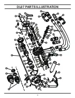
Страница 20: ...20 DL07 PARTS ILLUSTRATION ...

